Can the A20 line still be masked off on Haswell and successors?
Asked Answered
S

3

14

Wikipedia quotes this statement from Intel's manual

The functionality of A20M# is used primarily by older operating systems and not used by modern operating systems. On newer Intel 64 processors, A20M# may be absent.

It is a phrase that it is actually in the manual nowadays but it is ambiguous:

  1. Does A20M# actually refer to the pin only or to the whole masking thing?
  2. The A20M event/interrupt is named in the description of many instructions (e.g. TXT GETSEC or VMX instructions).

What I do know

The A20M# pin itself is gone, it was at some time replaced by the VLW (Virtual Legacy Wire) interface within the DMI. The DMI protocol is rich enough to have messages for asserting various legacy pin:

The PCH supports VLW messages as alternative method of conveying the status of the following legacy sideband interface signals to the processor: • A20M#, INTR, SMI#, INIT#, NMI

This quote comes from the PCH series 8 (Haswell era).


The PCH, up to these days, has an A20GATE Pass-Through functionality.
When the PCH is configured to trap the access to the legacy 8042 IO ports (60h, 64h) and deliver an SMI instead (for PS2 simulation of USB keyboards/mice), it can optionally let the A20 line enable sequence go through without being trapped.

Depending on how the PCH is configured, this allows either the EC (mobiles) or the SuperIO chip (desktops) to be the target of the command sequence.


Curiously enough, the PCH series 8 (Haswell era) datasheet, reports:

Note: A20M# functionality is not supported.

In the LPC section (where the EC/SuperIO are attached to), this, however, may only mean that the PCH itself doesn't emulate the A20 gate and an external chip (EC or SuperIO) must handle it.

It that were the case, the PCI must have a pin to be asserted by the external chip. The datasheet didn't mention any.

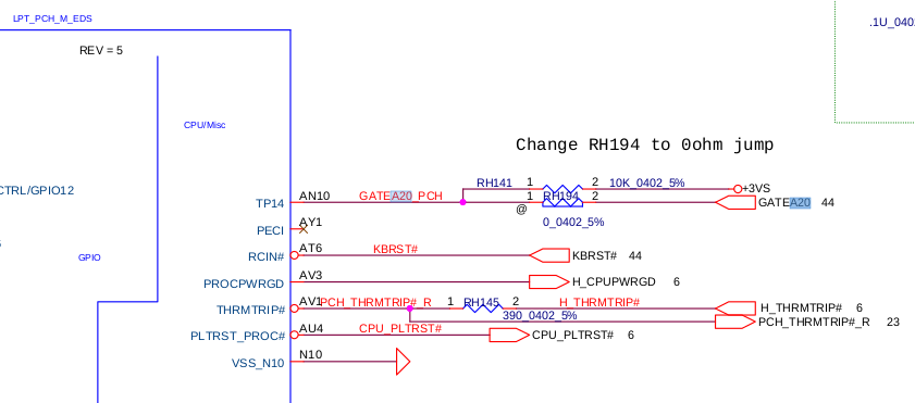
However, I've found the schematic of my previous Haswell laptop somewhere on a Chinese site and the schematic shows that the pin (actually the ball) AN10 (a.k.a. TP14) is used as the A20M input pin:

PCH input A20M pin

The blu box on the left is labeled as LYNX-POINT-DH82LPMS_BGA695.

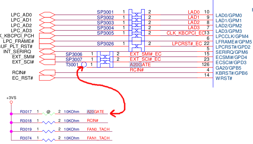
The other end of the GATEA20 signal comes from the EC (as expected):

EC GATEA20 output

The IT8586E/AX is an EC from Lenovo (apparently).

So the A20 line could still be masked off on Haswell platforms, unless I misinterpreted the schematics.

Thus, the datasheets are not complete regarding the A20M aspect. Probably the Intel's BIOS Writer Guide has it all.


What I want to know

Can the A20 line be disabled on, at least one, Haswell platform? What about Skylake and successors?

What I have done

I wrote a simple legacy boot loader that checks if the A20 line is enabled and try to disable it:

  1. If the A20 line is disabled, the test ends. The A20 gate functionality exists on the test platform.
  2. Otherwise, it asks the BIOS the supported A20 gate methods and then ask it to disable the A20 line (I trusted OSDev for the nomenclature of the functions, i.e. the enable vs disable-of-what thing, so I hope that call disables the A20 line and not the masking)
  3. In case the BIOS returned an error, the program disables the A20 line through the KBC, with the fast a20 method and with the port 0eeh method.
  4. Test again the A20 line status. If it is still enabled, disable it manually (unless it was done already) and test it once more.

When I run this on my Skylake laptop, the BIOS returned that only the fast A20 method was supported and signaled no error but yet the A20 line was still enabled. Even aver manually disabling it, the A20 line was still enabled.

I concluded that the A20 line cannot be disabled on Skylake, i.e. it doesn't exist anymore.

Sc answered 26/1, 2020 at 15:16 Comment(0)
H
3

VLW existed even before PCH as the 'IOAPIC virtual wire mode' which emulated the INTR input from 8259A over ICH DMI / APIC bus, as opposed to the LAPIC virtual wire mode which directed the 8259A INTR to the LINT pin INTR was hardwired to. The 'PIC mode' bypassed the LAPIC directly to the INTR pin to the BSP logical core.

And when the first PCH arrived, so Ibex Peak for Nehalem-EX, A20M# disappeared. It can now only be emulated by the PCH as a VLW A20M interrupt, and VLW is apparently an undocumented U2C (uncore to core) IDI opcode separate to IntLog/Phy. VLWs are broadcast to all cores by the Ubox/IIO (and internally to the LAPICs) in the same manner that the 2 CPU LINT pins are shared by all LAPICs (for INTR, NMI etc., only one processor should have an unmasked LINT entry (as ExtInt)) (and those LINT pins are connected directly to INTR exuding from 8259A, and NMI sources (PCH / DRAM), whereas the IOAPIC messages are PCI VLWs that travel over DMI, formerly over the APIC bus). IOH SAD used to contain QPIPNCB to filter VLWs further — assumedly it now exists in the IIO. I think the VLW is passed to the LVT LINT entry of the LINT pin that INTR it is virtually connected to and if LAPIC is disabled then it goes to INTR directly

A20GATE is driven to the PCH by the EC yes, and this causes the A20M VLW or A20M# pre-PCH (Port 92h also can trigger A20M#). A20M# is a separate pin to LINT and detection of A20M# happens at a macroinstruction boundary. Presumably the VLW is also absorbed by all cores, and interrupt all logical cores at the macroinstruction boundary. The A20M interrupt MSROM handler could be as simple as flushing and restarting the instruction flow with the current IP with a new setting enabled which changes the AGU address generation to mask the bit such that the address wraps round. As it's level sensitive, there will be another interrupt when it is deasserted.

On this Haswell M, A20GATE is still here as GA20 on the LPC interface, and it's also there on your Skylake U. I'm not sure whether it is connected or not on that schematic, there's no x on the wire and there's no directional net tags but the AG20GATE net label is there, which suggests it is connected, but I'm not sure what the big blue sort-of terminal symbol represents and what the difference is compared to a labelled wire without and compared to a wire with a tag symbol as well as a label. When it says A20M# is not supported it means the physical pin, but the IOAPIC generating a VLW is supported. A20GATE passthrough is supported meaning those devices can enable A20 masking.

Hypoxia answered 25/2, 2021 at 4:16 Comment(6)
Your research is appreciated, but it would be more useful to most readers if you'd summarize at the top, like "There's still a mechanism for A20gate on modern CPUs / chipsets, but it's not clear if it's always used". (Which I think might be what you're saying.) This wall of text seems to be the supporting reasoning for a simple answer, but you're missing any straightforward statement of what the answer is, at least anywhere that stands out.Alabama
Very interesting answer, especially the PCH<->Cores parts. I was aware that wires were replaced by the DMI protocol somehow but it's good to know the details. The EC<->PCH part, regarding the A20 Gate, is still dubious. There are the same symbols on both yours and my schematics and we both are unsure what they mean exactly. However, when a wire is connected it is marked with those red spikey rectangles (depending on if the signal is input, output, or both). The A20GATE signal from the EC goes into a blue circle (the other blue things belong to the two signals above, they overlap).Sc
I wrote that I tested enabling and disabling the A20 and found no difference, so I interpreted the absence of the red spikey rectangles as "The A20GATE is not a functional output signal of the EC/SuperIO".Sc
@MargaretBloom I didn't know that # meant low enabled i.e. it means the same as when there's a complement over the signal (which is the only nomenclature I knew), I thought it was just a convention to mean a physical rather than logical signal. I'm writing something currently that you might be able to correct me on: https://mcmap.net/q/830997/-what-is-the-difference-between-quot-soft-reset-quot-and-quot-hard-reset-quot-in-embedded-fieldHypoxia
I believe actually that the red spikey rectangle (pentagon) means that it is driven internally, driven externally (if facing outwards) and driven internally and externally (if it is a hexagon shape). I think the rectangle connects to an external rectangle with the same black label name as the black label and opposing rectangle, and then the red net name also additionally connects to some extension off the side of the schematic like a pull down resistor with the same red net name.Hypoxia
Having said that on the schematic im about to send for instance you sometimes see a black label and rectangle also going to the pulling resistor. You are right that A20GATE is not connected on that particular schematic I think because it's only connected to a pull up resistor as you show (which is the red net label), and does not have a rectangle with a black label to the PCH. It's connected on this cannon lake PCH to a 'BD connector' that causes a SMBALERT# which is incorrectly facing the wrong way on PCHHypoxia
S
6

It seems there is at least one Skylake platform where theA20 line cannot be disabled anymore.

Apart from my testing, I've picked up the first schematic of a Skylake laptop I could find online (Acer Swift SF314-51):

A20GATE signal connection

The thing on the right is the EC, which has an A20GATE connected/pulled up to +3VS.
I'm not really familiar with the symbols in this schematic but those are the only A20GATE traces present, there is no connection to the PCH.

Considering that (according to the datasheets) the PCH has no support for the A20 gate emulation, this seems a piece of strong evidence in favor of the absence of the A20 masking feature on this platform.

This reasoning is valid iif I've correctly understood the schematic and only proves that there exists recent x86 platforms where the A20 masking doesn't exist anymore.


I'll leave this question unanswered until somebody comes with a more complete answer.

Sc answered 27/1, 2020 at 16:16 Comment(0)
A
4

Section 8.7.13.4 (External Signal Compatibility) of volume 3 of the Intel SDM (April 2021 edition) says:

The functionality of A20M# is used primarily by older operating systems and not used by modern operating systems. On newer Intel 64 processors, A20M# may be absent.

(emphasis is mine).

It doesn't specify when this was removed, but you can assume that it will be unavailable starting from a certain point.

Ambassadress answered 7/12, 2021 at 10:51 Comment(0)
H
3

VLW existed even before PCH as the 'IOAPIC virtual wire mode' which emulated the INTR input from 8259A over ICH DMI / APIC bus, as opposed to the LAPIC virtual wire mode which directed the 8259A INTR to the LINT pin INTR was hardwired to. The 'PIC mode' bypassed the LAPIC directly to the INTR pin to the BSP logical core.

And when the first PCH arrived, so Ibex Peak for Nehalem-EX, A20M# disappeared. It can now only be emulated by the PCH as a VLW A20M interrupt, and VLW is apparently an undocumented U2C (uncore to core) IDI opcode separate to IntLog/Phy. VLWs are broadcast to all cores by the Ubox/IIO (and internally to the LAPICs) in the same manner that the 2 CPU LINT pins are shared by all LAPICs (for INTR, NMI etc., only one processor should have an unmasked LINT entry (as ExtInt)) (and those LINT pins are connected directly to INTR exuding from 8259A, and NMI sources (PCH / DRAM), whereas the IOAPIC messages are PCI VLWs that travel over DMI, formerly over the APIC bus). IOH SAD used to contain QPIPNCB to filter VLWs further — assumedly it now exists in the IIO. I think the VLW is passed to the LVT LINT entry of the LINT pin that INTR it is virtually connected to and if LAPIC is disabled then it goes to INTR directly

A20GATE is driven to the PCH by the EC yes, and this causes the A20M VLW or A20M# pre-PCH (Port 92h also can trigger A20M#). A20M# is a separate pin to LINT and detection of A20M# happens at a macroinstruction boundary. Presumably the VLW is also absorbed by all cores, and interrupt all logical cores at the macroinstruction boundary. The A20M interrupt MSROM handler could be as simple as flushing and restarting the instruction flow with the current IP with a new setting enabled which changes the AGU address generation to mask the bit such that the address wraps round. As it's level sensitive, there will be another interrupt when it is deasserted.

On this Haswell M, A20GATE is still here as GA20 on the LPC interface, and it's also there on your Skylake U. I'm not sure whether it is connected or not on that schematic, there's no x on the wire and there's no directional net tags but the AG20GATE net label is there, which suggests it is connected, but I'm not sure what the big blue sort-of terminal symbol represents and what the difference is compared to a labelled wire without and compared to a wire with a tag symbol as well as a label. When it says A20M# is not supported it means the physical pin, but the IOAPIC generating a VLW is supported. A20GATE passthrough is supported meaning those devices can enable A20 masking.

Hypoxia answered 25/2, 2021 at 4:16 Comment(6)
Your research is appreciated, but it would be more useful to most readers if you'd summarize at the top, like "There's still a mechanism for A20gate on modern CPUs / chipsets, but it's not clear if it's always used". (Which I think might be what you're saying.) This wall of text seems to be the supporting reasoning for a simple answer, but you're missing any straightforward statement of what the answer is, at least anywhere that stands out.Alabama
Very interesting answer, especially the PCH<->Cores parts. I was aware that wires were replaced by the DMI protocol somehow but it's good to know the details. The EC<->PCH part, regarding the A20 Gate, is still dubious. There are the same symbols on both yours and my schematics and we both are unsure what they mean exactly. However, when a wire is connected it is marked with those red spikey rectangles (depending on if the signal is input, output, or both). The A20GATE signal from the EC goes into a blue circle (the other blue things belong to the two signals above, they overlap).Sc
I wrote that I tested enabling and disabling the A20 and found no difference, so I interpreted the absence of the red spikey rectangles as "The A20GATE is not a functional output signal of the EC/SuperIO".Sc
@MargaretBloom I didn't know that # meant low enabled i.e. it means the same as when there's a complement over the signal (which is the only nomenclature I knew), I thought it was just a convention to mean a physical rather than logical signal. I'm writing something currently that you might be able to correct me on: https://mcmap.net/q/830997/-what-is-the-difference-between-quot-soft-reset-quot-and-quot-hard-reset-quot-in-embedded-fieldHypoxia
I believe actually that the red spikey rectangle (pentagon) means that it is driven internally, driven externally (if facing outwards) and driven internally and externally (if it is a hexagon shape). I think the rectangle connects to an external rectangle with the same black label name as the black label and opposing rectangle, and then the red net name also additionally connects to some extension off the side of the schematic like a pull down resistor with the same red net name.Hypoxia
Having said that on the schematic im about to send for instance you sometimes see a black label and rectangle also going to the pulling resistor. You are right that A20GATE is not connected on that particular schematic I think because it's only connected to a pull up resistor as you show (which is the red net label), and does not have a rectangle with a black label to the PCH. It's connected on this cannon lake PCH to a 'BD connector' that causes a SMBALERT# which is incorrectly facing the wrong way on PCHHypoxia

© 2022 - 2024 — McMap. All rights reserved.