Microservices are independently deployable components. Therefore, using a component diagram appears a very good intuition:
It specifies a Component as a modular unit with well-defined Interfaces that is replaceable within its environment. The Component concept addresses the area of component-based development and component-based system structuring (...).
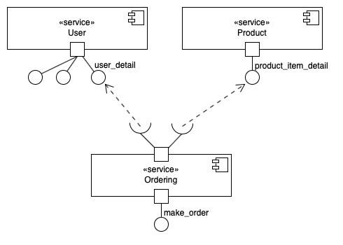
In your component diagram each microservice would be shown as a separate component with the stereotype «service». Since microservices do not just implement an interface but expose it via an endpoint, you should make use of ports:
Ports represent interaction points through which an EncapsulatedClassifier communicates with its environment.
Interfaces provided or required (lollipops and sockets) would be connected to ports. The port make the difference: without the port, lollipops and sockets could as well mean a realisation or a «use» dependency to an interface classifier within a big monolith!
In the end your diagram could look somewhat like: ![enter image description here]()
Additional thoughts:
If you hesitate between «service» and «subsystem» stereotype, you may consider creating your own UML profile that defines a «microservice» stereotype.
If in some complex diagram you do not want to show the detail of the service endpoints, you may just use an assembly connector without socket/lollipop except where you want to put the focus.
Similarly, if you are mainly interested in the dependency, you may just show the component and their dependency relation (since components are classifiers).
If you think of microservices, you will inevitably think of scaling strategies, such as for example having several instances of the same service running on several containers/servers, or heving several instances of the same microservice partition the data. This kind of though is about deployment scenarios of the components. You may then consider deployment diagrams. But this goes far beyond your question.

