Remove noisy lines from an image
Asked Answered
Z

2

15

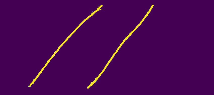
I have images that are noised with some random lines like the following one:
enter image description here
I want to apply on them some preprocessing in order to remove the unwanted noise ( the lines that distort the writing) so that I can use them with OCR (Tesseract).
The idea that came to my mind is to use dilation to remove the noise then use erosion to fix the missing parts of the writing in a second step.
For that, I used this code:

import cv2
import numpy as np

img = cv2.imread('linee.png', cv2.IMREAD_GRAYSCALE)
kernel = np.ones((5, 5), np.uint8)
img = cv2.dilate(img, kernel, iterations=1)
img = cv2.erode(img, kernel, iterations=1)
cv2.imwrite('delatedtest.png', img)

Unfortunately, the dilation didn't work well, The noise lines are still existing.

enter image description here
I tried changing the kernel shape, but it got worse: the writing were partially or completely deleted.
I also found an answer saying that it is possible to remove the lines by

turning all black pixels with two or less adjacent black pixels to white.

That seems a bit complicated for me since I am beginner to computer vision and opencv.
Any help would be appreciated, thank you.

Zealand answered 3/1, 2019 at 19:17 Comment(4)
erode removes the thinnest parts first ... you can see that if you look carefully. The lines are about as thick as your text - if you erode/dilatate them away, your text will be gone. generally you erode first to get rid of tiny things, then dilatate again to make survivers thicker again ... you use them the other way round. why?Displode
Despite the image being defaced, have you tried running it through the OCR to check the results?Godewyn
@PatrickArtner I tried using dilation first then erosion and I also tried using erosion first then dilation, but didn't work too.Zealand
@WaynePhipps yeah I tried, but it gave nothing, the output was emptyZealand
F
17

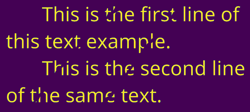
Detecting lines like these is what the path opening was invented for. DIPlib has an implementation (disclosure: I implemented it there). As an alternative, you can try using the implementation by the authors of the paper that I linked above. That implementation does not have the "constrained" mode that I use below.

Here is a quick demo for how you can use it:

import diplib as dip
import matplotlib.pyplot as pp

img = 1 - pp.imread('/home/cris/tmp/DWRTF.png')
lines = dip.PathOpening(img, length=300, mode={'constrained'})

Here we first inverted the image because that makes other things later easier. If not inverting, use a path closing instead. The lines image:

lines

Next we subtract the lines. A small area opening removes the few isolated pixels of the line that were filtered out by the path opening:

text = img - lines
text = dip.AreaOpening(text, filterSize=5)

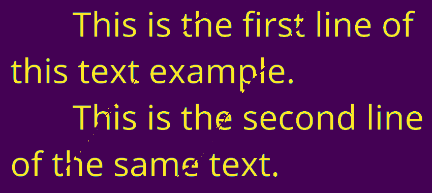
text

However, we've now made gaps in the text. Filling these up is not trivial. Here is a quick-and-dirty attempt, which you can use as a starting point:

lines = lines > 0.5
text = text > 0.5
lines -= dip.BinaryPropagation(text, lines, connectivity=-1, iterations=3)
img[lines] = 0

final result

Fiscal answered 3/1, 2019 at 20:16 Comment(7)
Sorry, I have a question: PyDIP works perfectly, but sometimes, it gives me this error: Traceback (most recent call last): File "pydoc.py", line 5, in <module> lines = dip.PathOpening(img, length=300, mode={'constrained'}) RuntimeError: Image is not scalar in function: void dip::PathOpening(const dip::Image&, const dip::Image&, dip::Image&, dip::uint, const String&, const StringSet&) (/home/hani/cert/pydip/diplib/src/morphology/pathopening.cpp at line number 396) Do you have any idea about the reason of this error? Can it be the image resolution?Zealand
@test: “Image is not scalar” means that the image has more than one channel, but only scalar (single-channel) images are allowed in morphological functions at the moment. I presume you have an RGB image. You should convert it to gray-scale, for example by dip.ColorSpaceManager.Convert(img, 'gray').Fiscal
Sorry for disturbing, but I got this error: RuntimeError: Image's number of tensor elements and color space are inconsistent in function: void dip::ColorSpaceManager::Convert(const dip::Image&, dip::Image&, const String&) const (/home/hani/cert/pydip/diplib/src/color/color.cpp at line number 234).Zealand
@test: Do img = dip.Image(img). Now what does img.TensorElements() return? And what does img.ColorSpace() return? Maybe you have 3 tensor elements (==channels) but the color space is an empty string? If so, do img.SetColorSpace('RGB'), then you'll be able to convert to gray. The other option is to do img=img.TensorElement(0) to just extract the first channel. -- Obviously this area hadn't been user-tested very extensively yet. :) I'll look into improving the usability. Thanks for pointing this out!Fiscal
You are right, img.TensorElements() returns 4 and img.ColorSpace() returned an empty string. I did as you explained and it worked correctly. I also converted the image to grayscale using opencv img = cv2.imread('img.png', 0) then save it before I use PyDIP and this worked well too. Thank you so much for your help and explanation.Zealand
@test: Awesome! You should be able to directly use the image as read by OpenCV in PyDIP too, no need to first save it. Just use OpenCV imread instead of pyplot imread.Fiscal
Thank you for making this library open source and thank you again for explaining how to use it!Zealand
R
7

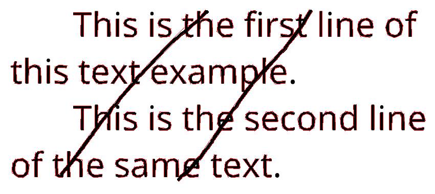
You can do that using createLineSegmentDetector(), a function from opencv

import cv2

#Read gray image
img = cv2.imread("lines.png",0)

#Create default parametrization LSD
lsd = cv2.createLineSegmentDetector(0)

#Detect lines in the image
lines = lsd.detect(img)[0] #Position 0 of the returned tuple are the detected lines

#Draw the detected lines
drawn_img = lsd.drawSegments(img,lines)

#Save the image with the detected lines
cv2.imwrite('lsdsaved.png', drawn_img)

enter image description here
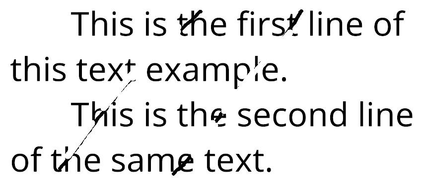
The next part of the code will delete only the lines which their length is more than 50 pixels:

for element in lines:

  #If the length of the line is more than 50, then draw a white line on it
  if (abs(int(element[0][0]) - int(element[0][2])) > 50 or abs(int(element[0][1]) - int(element[0][3])) > 50): 

    #Draw the white line
    cv2.line(img, (int(element[0][0]), int(element[0][1])), (int(element[0][2]), int(element[0][3])), (255, 255, 255), 12)

#Save the final image
cv2.imwrite('removedzz.png', img)

enter image description here

Well, it didn't work perfectly with the current image, but it may give better results with different images. You can adjust the length of the lines to remove and the thickness of the white lines to draw insteaad of the removed lines.
I hope it helps.

Raybourne answered 6/1, 2019 at 20:30 Comment(0)

© 2022 - 2024 — McMap. All rights reserved.