Controlling simple relay switch via USB
Asked Answered
I

6

15

I'm looking to control a mains powered light from a simple relay switch connected via USB to the computer.

The relay switch isn't even a USB device, it's just a simple switch that requires the USB voltage to turn it on. When the voltage drops below a threshold, the switch will turn the light off.

My problem is that I can't control the power output of a USB port. I'm happy to do it using any language on Windows or Linux (but preferably Java because I'm used to it).

Inefficiency answered 14/7, 2010 at 12:32 Comment(0)
E
17

Unfortunately, in most cases you cannot control the power supply to the USB port. The power supply is usually hardwired through, and not switchable in software. You can send a reset to a USB device, but that won't work in your case.

There are a number of projects on instructables that do similar to what you describe, but unfortunately they seem to either be quite complicated or require expensive parts.

EDIT: There is actually a product currently in the news which would do want you want, but it doesn't appear to be shipping yet: http://www.pwrusb.com/

EDIT (again): Apparently you can do this with some usb hubs. This post sugggests the Linksys USB2HUB4 is one that works.

EDIT (and again): Apparently there are a number of similar questions, but there don't seem to be any more useful answers:

Easterly answered 14/7, 2010 at 13:11 Comment(0)
A
5

Most of the USB to Serial or USB to RS232 $10 converters support hardware handshaking. Use one of those as a single channel digital io.

Connect your transistor that will drive the relay to DTR on the converter board and command DTR ON/OFF with the converters driver.

A 2N7002 is a good transistor to use (FET actually) since it will work from 3V and doesnt need any resistors anywhere.

Arched answered 9/10, 2014 at 4:56 Comment(0)
I
2

Here is a complete solution.

It uses an Arduino board, with a USB connection, (and Uno for example) to control the relay and combines this with pfod (Protocol for Operation Discovery) www.pfod.com.au which will let you control the board/relay from either the Arduino IDE SerialMonitor, or a terminal window (TeraTerm) or a Java program. The message protocol encloses commands in { }, think simplified html for micros, and provides numerous screens, menus, sliders, text and numeric inputs, etc. A detailed protocol spec is available

See Garage Door Remote for a detailed example, with full Arduino code and an example of controlling the relay from TeraTerm as well as the Arduino IDE SerialMonitor.

There is also an Android app, pfodApp, which will do general purpose control via bluetooth, or wifi/internet with 128 bit security. The pfodApp does all the Android stuff, you only need to code some simple strings in your Arduino code to get any menu system you want. See www.pfod.com.au for numerous examples.

Incorporable answered 15/12, 2013 at 21:14 Comment(0)
A
2

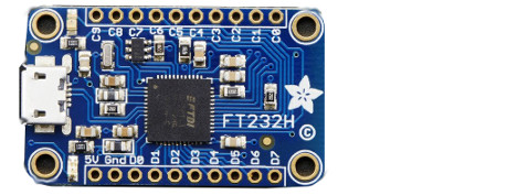
You need a USB-GPIO microcontroller:

Adafruit FT232H (about $15) enter image description here

Arduino Nano ATmega328 (about $7) 2

See this answer

Avelin answered 6/6, 2017 at 2:59 Comment(0)
L
0

I would suggest placing a separate Raspberry Pi unit with a wake-on-lan feature activated so you can ping it off and on.

Langston answered 1/2, 2014 at 22:55 Comment(2)
Could you provide documentation or a tutorial on how setup wake-on-LAN with Raspberries?Schock
As a RPi owner I am not aware that the RPi Wired LAN connection provided by a MicroChip LAN9512 (2-USB port B models) or LAN9514 (4-USB Port B+ models) is wired up in software/firmware/hardware - though the IC does have wake-on-LAN capabilities so it might be interesting to see if it can be done...!Odont
S
0

You could do it by combining these two products from Pololu, for about $25:

  1. Micro Maestro (assembled)
  2. Basic SPDT Relay Carrier with 5VDC Relay (Assembled)

The Maestro is mainly a servo controller but you can set any of its channels to be simple digital outputs instead. The output can be controlled from the Maestro Control Center software or you can write your own software. A digital output from a Maestro is suitable to turn on the relay on the relay carrier. The relay could be powered from USB through the Maestro; I think it draws about 100 mA of current so that probably will not be a problem for most USB ports, though it would not be USB-compliant because the total current drawn by the Maestro and the relay would be over 100 mA. You could supply your own power source for the relay if you are worried about that.

Samuels answered 2/2, 2014 at 9:13 Comment(0)

© 2022 - 2024 — McMap. All rights reserved.