I am trying to write an STM32 as an I2C slave device with a simple interface that works like this:
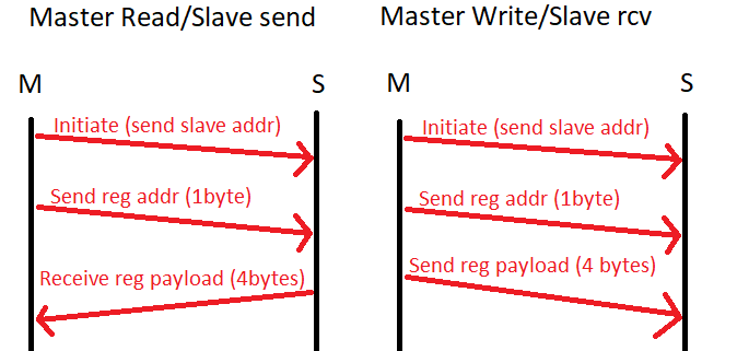
So master will always send a registered address every time, then either write or read from that register address.
The slave then needs to always receive 1 byte for a registered address, then it either sends what information is in that register back to the master if the next operation is a read or overwrites the register if the master's next operation is another write.
When I run my code however, I get some NACKS where ther should be ACKS
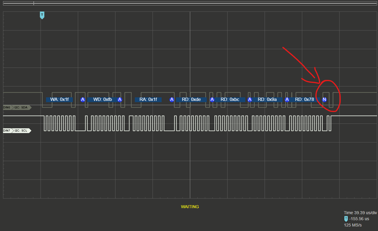
Here is the response when the master requests a buffer:
You can see the NACK at the end right after the slave finishes sending the last byte
This is a bit of a pain but the master receives the data ok so i can live with this
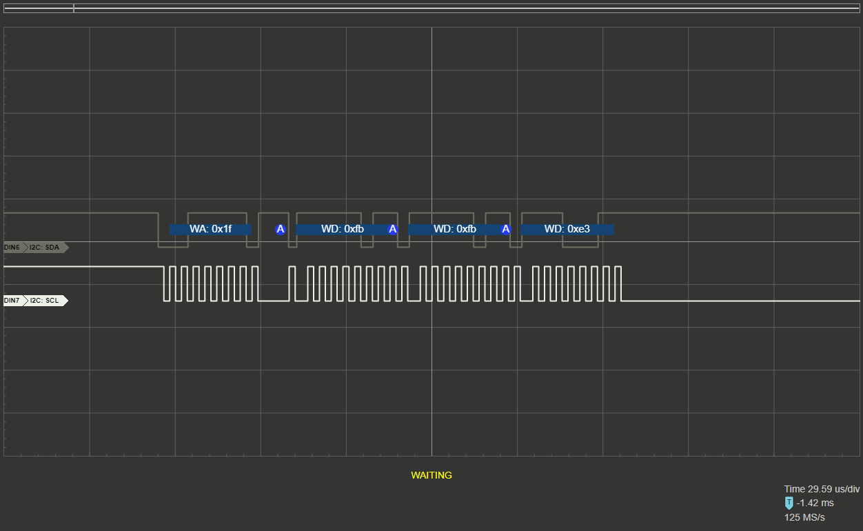
However when i try to write to a register on the slave this is what comes out:
Slave receives register address, then receives 1 byte and ack, then after receiving the second byte for some reason it just holds the line up (I need to use clock stretching here)
This is not ok, not only the slave didnt receive all the data but it also locks the line for any further communications. Why Am i having this? im scratching my head for months on this at this point
 Here is the master code just for reference (running on a simple Arduino) since the focus is really on the STM32 slave code:
#include <Wire.h>

uint16_t read_register(int devAddr, unsigned char regAddr, unsigned char bytes, unsigned char * buffer){
  unsigned char i = 0;
  Wire.beginTransmission(devAddr);
  Wire.write(regAddr);
  Wire.endTransmission(false);
  Wire.requestFrom(devAddr, bytes , true);
  while(Wire.available()){
    buffer[i] = Wire.read();
    i++;
  }
  return true;
}

uint16_t write_register(int devAddr, unsigned char regAddr, unsigned char bytes, unsigned char * buffer){
  unsigned char i = 0;
  Wire.beginTransmission(devAddr);
  Wire.write(regAddr); // Reg to write
  for(i = 0; i < bytes; i++){
    Wire.write(buffer[i]);
  }
  Wire.endTransmission(true);
  return true;
}

void setup()
{
  Wire.begin();
  Wire.setClock(400);
  Serial.begin(9600);
  while (!Serial);             // Leonardo: wait for serial monitor
  Serial.println("Starting");
}


void loop()
{
  unsigned char buffSize = 4;
  unsigned char readBuff[buffSize];
  unsigned char writeBuff[5] = {0xFB, 0xE3, 0XE2, 0xE1, 0xE0};


  for (int i = 0; i < buffSize; i++) readBuff[i] = 0;
  read_register(0x1F, 251, buffSize, readBuff);
  Serial.print(readBuff[3], HEX);
  Serial.print(readBuff[2], HEX);
  Serial.print(readBuff[1], HEX);
  Serial.println(readBuff[0], HEX);

  write_register(0x1F, 0xFB, 5, writeBuff);

  delay(2000);
}
Here is the I2C code section of the STM32 slave:
/* USER CODE BEGIN Header */
/**
  ******************************************************************************
  * @file    i2c.c
  * @brief   This file provides code for the configuration
  *          of the I2C instances.
  ******************************************************************************
  * @attention
  *
  * Copyright (c) 2022 STMicroelectronics.
  * All rights reserved.
  *
  * This software is licensed under terms that can be found in the LICENSE file
  * in the root directory of this software component.
  * If no LICENSE file comes with this software, it is provided AS-IS.
  *
  ******************************************************************************
  */
/* USER CODE END Header */
/* Includes ------------------------------------------------------------------*/
#include "i2c.h"

/* USER CODE BEGIN 0 */

/* USER CODE END 0 */

I2C_HandleTypeDef hi2c1;

/* I2C1 init function */
void MX_I2C1_Init(void)
{

  /* USER CODE BEGIN I2C1_Init 0 */
  // Get I2C address code from hardware jumpers
  // Address starts at I2C_ADDRESS_BASE and is offset by value read on jumpers array
  uint8_t I2C_Address = 0x0;
  I2C_Address = (I2C_ADDRESS_BASE + (
          (HAL_GPIO_ReadPin(AD0_GPIO_Port, AD0_Pin) << 0)|
          (HAL_GPIO_ReadPin(AD1_GPIO_Port, AD1_Pin) << 1)|
          (HAL_GPIO_ReadPin(AD2_GPIO_Port, AD2_Pin) << 2)|
          (HAL_GPIO_ReadPin(AD3_GPIO_Port, AD3_Pin) << 3)
  )) << 1;
  /* USER CODE END I2C1_Init 0 */

  /* USER CODE BEGIN I2C1_Init 1 */

  /* USER CODE END I2C1_Init 1 */
  hi2c1.Instance = I2C1;
  hi2c1.Init.Timing = 0x0000020B;
  hi2c1.Init.OwnAddress1 = I2C_Address;
  hi2c1.Init.AddressingMode = I2C_ADDRESSINGMODE_7BIT;
  hi2c1.Init.DualAddressMode = I2C_DUALADDRESS_ENABLE;
  hi2c1.Init.OwnAddress2 = (I2C_ADDRESS_BASE + 16) << 1;
  hi2c1.Init.OwnAddress2Masks = I2C_OA2_NOMASK;
  hi2c1.Init.GeneralCallMode = I2C_GENERALCALL_DISABLE;
  hi2c1.Init.NoStretchMode = I2C_NOSTRETCH_DISABLE;
  if (HAL_I2C_Init(&hi2c1) != HAL_OK)
  {
    Error_Handler();
  }

  /** Configure Analogue filter
  */
  if (HAL_I2CEx_ConfigAnalogFilter(&hi2c1, I2C_ANALOGFILTER_ENABLE) != HAL_OK)
  {
    Error_Handler();
  }

  /** Configure Digital filter
  */
  if (HAL_I2CEx_ConfigDigitalFilter(&hi2c1, 0) != HAL_OK)
  {
    Error_Handler();
  }
  /* USER CODE BEGIN I2C1_Init 2 */

  /* USER CODE END I2C1_Init 2 */

}

void HAL_I2C_MspInit(I2C_HandleTypeDef* i2cHandle)
{

  GPIO_InitTypeDef GPIO_InitStruct = {0};
  if(i2cHandle->Instance==I2C1)
  {
  /* USER CODE BEGIN I2C1_MspInit 0 */

  /* USER CODE END I2C1_MspInit 0 */

    __HAL_RCC_GPIOB_CLK_ENABLE();
    /**I2C1 GPIO Configuration
    PB6     ------> I2C1_SCL
    PB7     ------> I2C1_SDA
    */
    GPIO_InitStruct.Pin = GPIO_PIN_6|GPIO_PIN_7;
    GPIO_InitStruct.Mode = GPIO_MODE_AF_OD;
    GPIO_InitStruct.Pull = GPIO_NOPULL;
    GPIO_InitStruct.Speed = GPIO_SPEED_FREQ_HIGH;
    GPIO_InitStruct.Alternate = GPIO_AF4_I2C1;
    HAL_GPIO_Init(GPIOB, &GPIO_InitStruct);

    /* I2C1 clock enable */
    __HAL_RCC_I2C1_CLK_ENABLE();

    /* I2C1 interrupt Init */
    HAL_NVIC_SetPriority(I2C1_EV_IRQn, 5, 0);
    HAL_NVIC_EnableIRQ(I2C1_EV_IRQn);
    HAL_NVIC_SetPriority(I2C1_ER_IRQn, 5, 0);
    HAL_NVIC_EnableIRQ(I2C1_ER_IRQn);
  /* USER CODE BEGIN I2C1_MspInit 1 */

  /* USER CODE END I2C1_MspInit 1 */
  }
}

void HAL_I2C_MspDeInit(I2C_HandleTypeDef* i2cHandle)
{

  if(i2cHandle->Instance==I2C1)
  {
  /* USER CODE BEGIN I2C1_MspDeInit 0 */

  /* USER CODE END I2C1_MspDeInit 0 */
    /* Peripheral clock disable */
    __HAL_RCC_I2C1_CLK_DISABLE();

    /**I2C1 GPIO Configuration
    PB6     ------> I2C1_SCL
    PB7     ------> I2C1_SDA
    */
    HAL_GPIO_DeInit(GPIOB, GPIO_PIN_6);

    HAL_GPIO_DeInit(GPIOB, GPIO_PIN_7);

    /* I2C1 interrupt Deinit */
    HAL_NVIC_DisableIRQ(I2C1_EV_IRQn);
    HAL_NVIC_DisableIRQ(I2C1_ER_IRQn);
  /* USER CODE BEGIN I2C1_MspDeInit 1 */

  /* USER CODE END I2C1_MspDeInit 1 */
  }
}

/* USER CODE BEGIN 1 */

#define I2C_BUFFER_SIZE 8
uint8_t i2c_buffer[I2C_BUFFER_SIZE];
uint8_t reg_addr_rcvd = 0;
#define I2C_REG_ADD_SIZE        1
#define I2C_PAYLOAD_SIZE        4

extern void HAL_I2C_AddrCallback(I2C_HandleTypeDef *hi2c, uint8_t TransferDirection, uint16_t AddrMatchCode){
    UNUSED(AddrMatchCode);
    // If is master write, listen to necessary amount of bytes
    if(TransferDirection == I2C_DIRECTION_TRANSMIT){
        // First write request is always 1 byte of the requested reg address
        // Will saved it on the first position of I2C_buffer
        if(!reg_addr_rcvd){
            HAL_I2C_Slave_Sequential_Receive_IT(hi2c, (void*)i2c_buffer, I2C_REG_ADD_SIZE, I2C_FIRST_FRAME);

        } else {
            // If a subsequent write request is sent, will receve 4 bytes from master
            // Save it on the rest of the buffer
            HAL_I2C_Slave_Sequential_Receive_IT(hi2c, (void*)i2c_buffer, I2C_PAYLOAD_SIZE, I2C_NEXT_FRAME);
        }
    }
    else {
        // If a read request is sent by the master, return the value of the data in the requested register that was saved on 1st
        // position of the I2C buffer
        HAL_I2C_Slave_Sequential_Transmit_IT(hi2c, data_register[i2c_buffer[0]].mem_addr, data_register[i2c_buffer[0]].len, I2C_LAST_FRAME);
    }
    // Read address + data size. If it is a read command, data size will be zero
}


extern void HAL_I2C_SlaveRxCpltCallback(I2C_HandleTypeDef *hi2c){
    // This is called after a master 'write' request. first time around it will be a register.
    // Second time if its a write to register request, it will be a payload
    if(!reg_addr_rcvd){
        // If reg_addr_rcvd is false, means that it received a register
        reg_addr_rcvd = 1;
    } else {
        // If reg_addr_rcvd is set, means that this callback was returned after the payload data has been received
        reg_addr_rcvd = 0;
    }
    HAL_I2C_EnableListen_IT(hi2c);
    HAL_GPIO_TogglePin(LED_G_GPIO_Port, LED_G_Pin);
}

extern void HAL_I2C_ListenCpltCallback (I2C_HandleTypeDef *hi2c){
    HAL_I2C_EnableListen_IT(hi2c);
    HAL_GPIO_TogglePin(LED_B_GPIO_Port, LED_B_Pin);
}

extern void HAL_I2C_SlaveTxCpltCallback(I2C_HandleTypeDef *hi2c){
    // Reset reg_addr_rcvd after finish sending requested register
    reg_addr_rcvd = 0;
    HAL_I2C_EnableListen_IT(hi2c);
}


extern void HAL_I2C_ErrorCallback(I2C_HandleTypeDef *hi2c)
{
    HAL_GPIO_TogglePin(LED_R_GPIO_Port, LED_R_Pin);
    //HAL_I2C_ERROR_NONE       0x00000000U    /*!< No error           */
    //HAL_I2C_ERROR_BERR       0x00000001U    /*!< BERR error         */
    //HAL_I2C_ERROR_ARLO       0x00000002U    /*!< ARLO error         */
    //HAL_I2C_ERROR_AF         0x00000004U    /*!< Ack Failure error  */
    //HAL_I2C_ERROR_OVR        0x00000008U    /*!< OVR error          */
    //HAL_I2C_ERROR_DMA        0x00000010U    /*!< DMA transfer error */
    //HAL_I2C_ERROR_TIMEOUT    0x00000020U    /*!< Timeout Error      */
    uint32_t error_code = HAL_I2C_GetError(hi2c);
    if (error_code != HAL_I2C_ERROR_AF){}
    HAL_I2C_EnableListen_IT(hi2c);
}
/* USER CODE END 1 */
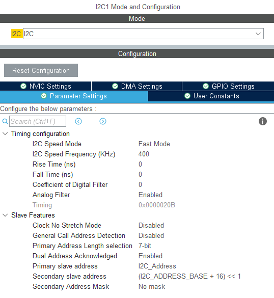
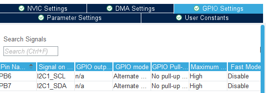
And here is cubeMX config for the I2C slave

Appreciate any insigth you guys could have. Thank you!
