How do I order subgraph clusters when using dot?
Asked Answered
S

2

5

I have a dot file in which I create subgraph clusters which I want to appear in a specific order, let's say I have this:

digraph G {
    splines=true;
    sep="+25,25";
    overlap=scalexy;
    nodesep=0.6;
    subgraph cluster_2 {
        label="ADD_MORE_PROBLEMS";
        subgraph cluster_3 {
            label="pattern";
            N1 [label="problem"];
        }
        subgraph cluster_4 {
            label="replacement";
            N2 [label="problem"];
            N3 [label="problem"];
        }
    }
}

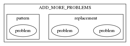
Which creates:

output from dot

How do I ensure that "pattern" appears to the left of "replacement" (I may have an arbitrary number of subgraphs).

Singular answered 26/2, 2017 at 1:16 Comment(3)
Just a clarification, in the file there are several top level clusters and those do in fact appear left to right as expected.Singular
reversing the order of your internal clusters seems to give the figure you want. More generally, it seems that subgraphs appear first at the right to the left as the appear in the code.Bohun
Thanks. Eventually I also wanted to have nested subgraphs and things started getting out of control. I ended up rendering each subgraph and then compositing the individual images in the right order.Singular
V
4

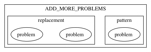
Clusters are one of the odd cases where simply the ordering in the code makes most (if not quite all) of the difference. If we simply reorder your code like this:

digraph G {
    splines=true;
    sep="+25,25";
    overlap=scalexy;
    nodesep=0.6;
    subgraph cluster_2 {
        label="ADD_MORE_PROBLEMS";
        subgraph cluster_4 {
            label="replacement";
            N2 [label="problem"];
            N3 [label="problem"];
        }
        subgraph cluster_3 {
            label="pattern";
            N1 [label="problem"];
        }
    }
}

that makes all the difference.The "ADD_MORE_PROBLEMS" cluster contains both the "pattern" cluster and the "replacement" cluster. The "pattern" cluster is to the left of the "replacement" cluster. The "pattern" cluster contains a single node, labeled 'problem'. The "replacement" cluster contains two nodes, both labeled 'problem'.

Now, that can fail, in which case setting up invisible edges is one of the more common solutions.

Valorievalorization answered 27/1, 2018 at 1:7 Comment(0)
L
4

I can't give and answer, but can provide some clarification. The usual approach to force layout is to introduce hidden edges. In this case, it does not work.

Without the nested clusters, you can use rank=same to force connected edges onto the same level. Then, an invisible edge N1 -> N2 [style = invis] would force the nodes into the correct ordering.

However, constraining nodes with rank breaks the cluster membership and prevents the scheme from working.

The modified graph shows the result. There may not be a general solution.

digraph G {
    splines=true;
    sep="+25,25";
    overlap=scalexy;
    nodesep=0.6;
    subgraph cluster_2 {
        label="ADD_MORE_PROBLEMS";
        subgraph cluster_3 {
            label="pattern";
            N1 [label="problem 1"];
        }
        subgraph cluster_4 {
            label="replacement";
            N2 [label="problem 2"];
            N3 [label="problem 3"];
        }
        // Introduce hidden edge (shown dashed)
        N1 -> N2 [style = dashed];
        // Force nodes to remain at same rank
        { rank = same; N1; N2; }
    }
}

Constrained luster ordering

Leprosy answered 7/7, 2017 at 5:59 Comment(0)
V
4

Clusters are one of the odd cases where simply the ordering in the code makes most (if not quite all) of the difference. If we simply reorder your code like this:

digraph G {
    splines=true;
    sep="+25,25";
    overlap=scalexy;
    nodesep=0.6;
    subgraph cluster_2 {
        label="ADD_MORE_PROBLEMS";
        subgraph cluster_4 {
            label="replacement";
            N2 [label="problem"];
            N3 [label="problem"];
        }
        subgraph cluster_3 {
            label="pattern";
            N1 [label="problem"];
        }
    }
}

that makes all the difference.The "ADD_MORE_PROBLEMS" cluster contains both the "pattern" cluster and the "replacement" cluster. The "pattern" cluster is to the left of the "replacement" cluster. The "pattern" cluster contains a single node, labeled 'problem'. The "replacement" cluster contains two nodes, both labeled 'problem'.

Now, that can fail, in which case setting up invisible edges is one of the more common solutions.

Valorievalorization answered 27/1, 2018 at 1:7 Comment(0)

© 2022 - 2024 — McMap. All rights reserved.