I'm using Embarcadero RAD Studio XE7 to create a C++ graphical application in which I'm trying to animate a circular progress using GDI+ and some dash pattern properties.
The idea is very simple: by configuring a pattern where the dash is long enough to fill the circumference of a circle, and where the blank part is long enough to prevent that two dashes are visible together on the circle, it is possible to show a circular progress where the dash offset property may be used to display the current progress position.
However, I'm unable to reaching my goal with GDI+, because several graphical artifacts are visible, and I'm unable to find a solution to resolve them. I'm pretty sure that the values I use are correct, because the exactly same drawing processed by Direct2D works fine.
Here is a sample code showing the issue. One circle is drawn with GDI+, the other with Direct2D. The drawing configuration are exactly the same for the 2 circles.
// fill the background
TRect rect(0, 0, ClientWidth, ClientHeight);
Canvas->Brush->Color = clWhite;
Canvas->Brush->Style = bsSolid;
Canvas->FillRect(rect);

const float startY     =  100.0f;
const float penWidth   =  32.0f;
const float dashOffset = -559.0f + (float(tb1->Position) * 559.0f * 0.01f);

std::vector<float> dashPattern;
dashPattern.push_back(559.0f / penWidth);
dashPattern.push_back(559.0f / penWidth);

// --------------------------------- USING GDI+ --------------------------------------

// create a GDI+ path showing a circle
Gdiplus::GraphicsPath path;
path.StartFigure();
path.AddBezier(Gdiplus::PointF(99.99999, 11.05255 + startY),
               Gdiplus::PointF(51.31296, 11.05255 + startY),
               Gdiplus::PointF(11.05254, 51.31297 + startY),
               Gdiplus::PointF(11.05254, 100 + startY));
path.AddBezier(Gdiplus::PointF(11.05254, 100 + startY),
               Gdiplus::PointF(11.05254, 148.6871 + startY),
               Gdiplus::PointF(51.31297, 188.9475 + startY),
               Gdiplus::PointF(99.99999, 188.9475 + startY));
path.AddBezier(Gdiplus::PointF(99.99999, 188.9475 + startY),
               Gdiplus::PointF(148.687,  188.9475 + startY),
               Gdiplus::PointF(188.9474, 149.1552 + startY),
               Gdiplus::PointF(188.9474, 100 + startY));
path.AddBezier(Gdiplus::PointF(188.9474, 100 + startY),
               Gdiplus::PointF(188.9474, 50.84483 + startY),
               Gdiplus::PointF(149.1552, 11.05255 + startY),
               Gdiplus::PointF(99.99998, 11.05255 + startY));
path.CloseFigure();

// configure the GDI+ pen
Gdiplus::Pen pen(Gdiplus::Color(255, 0, 0, 0));
pen.SetWidth(penWidth);
pen.SetDashOffset(dashOffset / penWidth);

const Gdiplus::LineCap lineCapStart = Gdiplus::LineCapFlat;
const Gdiplus::LineCap lineCapEnd   = Gdiplus::LineCapFlat;
const Gdiplus::DashCap dashCap      = Gdiplus::DashCapFlat;

pen.SetLineCap(lineCapStart, lineCapEnd, dashCap);

const Gdiplus::LineJoin lineJoin = Gdiplus::LineJoinMiter;
pen.SetLineJoin(lineJoin);
pen.SetMiterLimit(4.0f);

// configure dash style to custom (meaning that dash pattern should be used)
pen.SetDashStyle(Gdiplus::DashStyleCustom);

// configure dash pattern
pen.SetDashPattern(&dashPattern[0], dashPattern.size());

// draw the path using GDI+
Gdiplus::Graphics graphics(Canvas->Handle);
graphics.DrawPath(&pen, &path);

// ------------------------------- USING DIRECT2D ------------------------------------

const float startX = 300.0f;

// get a Direct2D canvas
TRect canvasRect(0, 0, ClientWidth, ClientHeight);
TDirect2DCanvas* pCanvas = new TDirect2DCanvas(Canvas->Handle, canvasRect);

// begin draw
pCanvas->BeginDraw();

ID2D1Factory* pD2DFactory;

// get factory associated with canvas
pCanvas->RenderTarget->GetFactory(&pD2DFactory);

// create a Direct2D path showing a circle
ID2D1PathGeometry* pGeometry;
pD2DFactory->CreatePathGeometry(&pGeometry);

ID2D1GeometrySink* pSink;
pGeometry->Open(&pSink);
pSink->BeginFigure(D2D1::Point2F(99.99999 + startX, 11.05255 + startY), D2D1_FIGURE_BEGIN_FILLED);
pSink->AddBezier(D2D1::BezierSegment(D2D1::Point2F(51.31296 + startX, 11.05255 + startY),
                                     D2D1::Point2F(11.05254 + startX, 51.31297 + startY),
                                     D2D1::Point2F(11.05254 + startX, 100 + startY)));
pSink->AddBezier(D2D1::BezierSegment(D2D1::Point2F(11.05254 + startX, 148.6871 + startY),
                                     D2D1::Point2F(51.31297 + startX, 188.9475 + startY),
                                     D2D1::Point2F(99.99999 + startX, 188.9475 + startY)));
pSink->AddBezier(D2D1::BezierSegment(D2D1::Point2F(148.687 + startX,  188.9475 + startY),
                                     D2D1::Point2F(188.9474 + startX, 149.1552 + startY),
                                     D2D1::Point2F(188.9474 + startX, 100 + startY)));
pSink->AddBezier(D2D1::BezierSegment(D2D1::Point2F(188.9474 + startX, 50.84483 + startY),
                                     D2D1::Point2F(149.1552 + startX, 11.05255 + startY),
                                     D2D1::Point2F(99.99998 + startX, 11.05255 + startY)));
pSink->EndFigure(D2D1_FIGURE_END_CLOSED);
pSink->Close();
pSink->Release();

// configure the Direct2D stroke properties
::D2D1_STROKE_STYLE_PROPERTIES strokeProps;
strokeProps.startCap   = D2D1_CAP_STYLE_FLAT;
strokeProps.endCap     = D2D1_CAP_STYLE_FLAT;
strokeProps.dashCap    = D2D1_CAP_STYLE_FLAT;
strokeProps.lineJoin   = D2D1_LINE_JOIN_MITER;
strokeProps.miterLimit = 4.0f;
strokeProps.dashStyle  = D2D1_DASH_STYLE_CUSTOM;
strokeProps.dashOffset = dashOffset / penWidth;

// get the stroke style to apply
ID2D1StrokeStyle* pStrokeStyle;
pD2DFactory->CreateStrokeStyle(strokeProps,
                               &dashPattern[0],
                               dashPattern.size(),
                               &pStrokeStyle);

::ID2D1SolidColorBrush* pSolidBrush;

::D2D1_COLOR_F color;
color.r = 0.0f;
color.g = 0.0f;
color.b = 0.0f;
color.a = 1.0f;

// create a solid color brush
pCanvas->RenderTarget->CreateSolidColorBrush(color, &pSolidBrush);

// draw the geometry
pCanvas->RenderTarget->DrawGeometry(pGeometry, pSolidBrush, penWidth, pStrokeStyle);

pCanvas->EndDraw();

delete pCanvas;
The tb1->Position property is just a track bar control cursor that can be moved between 0 to 100.
Using the above code, I noticed several differences between the 2 drawing:
When tb1->Position = 0, the GDI+ circle is fully visible whereas the Direct2D circle isn't visible (that is the correct effect I wanted to reach).
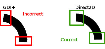
When tb1->Position is between 1 to 99, the GDI+ circle endings are drawn incorrectly.
![enter image description here]()
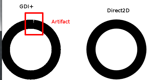
When tb1->Position = 100, a graphical artifact is visible on the GDI+ circle
![enter image description here]()
Unfortunately, using another library like Direct2D instead of GDI+ isn't an option for me. My question is: Why the above mentioned differences happen when I draw my dashed circle with GDI+? Am I doing something wrong, or is it a GDI+ bug?
IMPORTANT EDIT: On the above images, the antialiasing is enabled on the Direct2D drawing whereas it is disabled on the GDI+ drawing. This is not the issue. The above mentioned question is about graphical artifacts like the orientation of the segments endings, which are clearly different between GDI+ and Direct2D, or the blank artifact that appear while the circle is full. These issues happen with or without antialiasing.


