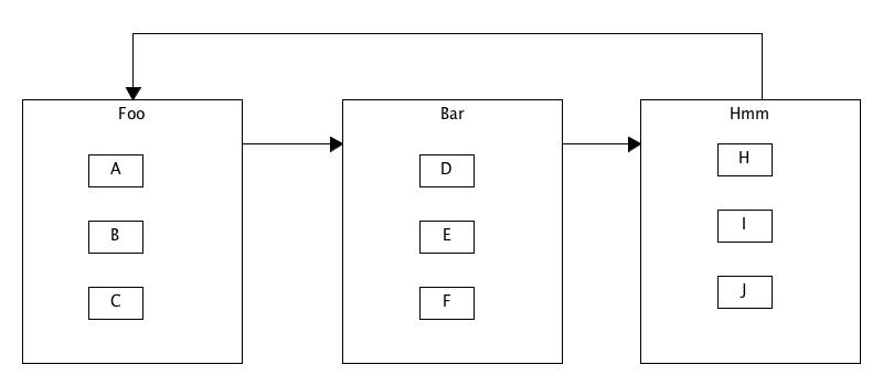
I am working on a JointJS graph, using DirectedGraph to take care of the layout and I am trying to achieve something similar to the image below. I need the nodes (A, B, C, D, E, F, G, H, I, J) to be "outlined" or enclosed in a separate node (Foo, Bar, Hmm). When I add all of the elements to the graph, everything is on top of each other. However, if I do not add the vertices between the regions, all the elements are laid out correctly, but without the vertices connecting the regions.
Based on the code below, what am I doing wrong? Do the nodes (A, B, C, D, E, F, G, H, I, J) cause an error because they are not connected to the rest of the graph?
Any feedback you could offer is much appreciated.
var graph = new joint.dia.Graph;
var paper = new joint.dia.Paper({
    el: $('#paper');
    width: 2000,
    height: 2000,
    gridSize: 1,
    model: graph
});

var regions = [ makeRegion('Foo'), makeRegion('Bar'), makeRegion('Hmm')];
var nodes = [
    makeNode('A'),
    makeNode('B'),
    makeNode('C'),
    makeNode('D'),
    makeNode('F'),
    makeNode('G'),
    makeNode('H'),
    makeNode('I'),
    makeNode('J'),
];
regions[0].embed(nodes[0]).embed(nodes[1]).embed(nodes[2]);
regions[1].embed(nodes[3]).embed(nodes[4]).embed(nodes[5]);
regions[2].embed(nodes[6]).embed(nodes[7]).embed(nodes[8]);
var vertices = [
    connect(regions[0], regions[1]),
    connect(regions[1], regions[2]),
    connect(regions[2], regions[0])
    ];
paper.addCells(regions.concat(nodes).concat(vertices));
joint.layout.DirectedGraph.layout(paper, {
    rankDir: 'LR',
    marginX: 30,
    marginY: 30,
    clusterPadding: {
        top: 30,
        left: 10,
        right: 10,
        bottom: 10
    }
});

function makeNode(name) {
    return new joint.shapes.basic.Rect({
        size: {
            width: 35,
            height: 35
        },
        attrs: {
            text: {
                text: name
            }
        }
    });
}

function connect(a, b) {
    return new joint.shapes.fsa.Arrow({
        source: { id: a.id },
        target: { id: b.id }
    });
}

function makeRegion(name) {
    return new joint.shapes.basic.Rect({
        size: {
            width: 300,
            height: 200
        },
        attrs: {
            text: {
                text: name
            }
        }
    });
}
EDIT:
While I never found a good solution to this problem, I did find that with some extra work, this can be achieved. It assumes that your graph is not too complex with few edges between regions.
If I added the edges separately, after all the nodes had been added to the graph, it would work ok. The directed layout, however, did not work exactly as intended. I used joint.layout.DirectedGraph.layout() initially so that it would align the internal nodes, and then I reposition the out regions. At the end I added the edges, and that produces results similar to the image above.
Here is a rough outline of how I achieved this:
var graph = new joint.dia.Graph;
var paper = new joint.dia.Paper({
    el: $('#paper');
    width: 2000,
    height: 2000,
    gridSize: 1,
    model: graph
});

var regions = [ makeRegion('Foo'), makeRegion('Bar'), makeRegion('Hmm')];
var nodes = [
    makeNode('A'),
    makeNode('B'),
    makeNode('C'),
    makeNode('D'),
    makeNode('F'),
    makeNode('G'),
    makeNode('H'),
    makeNode('I'),
    makeNode('J'),
];
regions[0].embed(nodes[0]).embed(nodes[1]).embed(nodes[2]);
regions[1].embed(nodes[3]).embed(nodes[4]).embed(nodes[5]);
regions[2].embed(nodes[6]).embed(nodes[7]).embed(nodes[8]);

paper.addCells(regions.concat(nodes));
joint.layout.DirectedGraph.layout(paper, {
    rankDir: 'LR',
    marginX: 30,
    marginY: 30,
    clusterPadding: {
        top: 30,
        left: 10,
        right: 10,
        bottom: 10
    }
});

var vertices = [
    connect(regions[0], regions[1]),
    connect(regions[1], regions[2]),
    connect(regions[2], regions[0])
    ];
repositionRegions();
// Add the edges after all the nodes are in their final position
graph.addCells(vertices);

function repositionRegions() {
    // Move regions to where you want them
}

function makeNode(name) {
    return new joint.shapes.basic.Rect({
        size: {
            width: 35,
            height: 35
        },
        attrs: {
            text: {
                text: name
            }
        }
    });
}

function connect(a, b) {
    return new joint.shapes.fsa.Arrow({
        source: { id: a.id },
        target: { id: b.id }
    });
}

function makeRegion(name) {
    return new joint.shapes.basic.Rect({
        size: {
            width: 300,
            height: 200
        },
        attrs: {
            text: {
                text: name
            }
        }
    });
}


Uncaught TypeError: Cannot read property 'isElement' of undefined– Volga