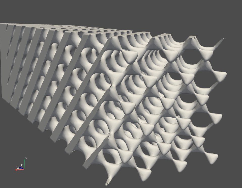
Here's a rough explanation of what I do in vtk:
- Create a surface (a minimal surface, not too relevant what it is, the geometry is important though: the gyroid has two labyrinths that are completely shut off from each other).
- use
vtkClipClosedSurfaceto shut off one of the labyrinths so that I get an object that has no open surfaces anymore. A regular surface looks like this, with a closed surface it looks like this.
Here's my problem: For more complicated versions of my structure, I get this:  Can you see how on the top left it works fine and near the bottom right it stops creating surfaces? Sometimes I also get really weird triangles in that last part.
To my understanding vtkClipClosedSurface knows from the surface normals where to close a surface and where not. The thing is: The normals of my structure are fine and they all point in the right direction. If you take a closer look on the structure you will notice that the lower part is basically an inversion of the top part that changes gradually, all in one surface.
I tried to modify my structure before cutting with many things like vtkSmoothPolyDataFilter, vtkCleanPolyData or vtkPolyDataNormals. I even tried extracting the boundary surfaces with vtkFeatureEdges, which led to an even worse result. Even vtkFillHolesFilter didn't yield any acceptable results. My surface seems flawless and easy enough to create a boundary.
I have no idea what else to try. This happens for other structures, too. Fixing it with a CAD tool is out of question, because it is supposed to work out of box. Please help me!
Here's another example of a geometry that doesn't close the surface properly. This time I used vtkFillHolesFilter which results in surfaces on the inside of the structure, while they should only occupy the boundary of te object.

In case you need a more detailed rundown of my pipeline, here goes:
- create surface using
mayavi.mlab.contour3d - get the
PolyDataby extracting theactor.mapper.input - convert format from
tvtkto regularvtk vtkClipClosedSurfacewith a plane collection that cuts away part of the structure (errors occur when the plane collection is the same as the structure boundary)- visualize it
Edit: Okay, this did not receive enough attention, so I constructed a minimal, complete and verifiable working example that reproduces the behaviour:
import numpy as np
import vtk  # VTK version 7.0
from mayavi import mlab  # mayavi version 4.4.4
from mayavi.api import Engine, OffScreenEngine
from tvtk.api import tvtk


def schwarz_D(x, y, z, linear_term=0):
        """This is the function for the Schwarz Diamond level surface."""
        return (np.sin(x) * np.sin(y) * np.sin(z) + np.sin(x) * np.cos(y) * np.cos(z) +
                np.cos(x) * np.sin(y) * np.cos(z) + np.cos(x) * np.cos(y) * np.sin(z)) - linear_term * z


def plane_collection(xn, x, yn, y, zn, z):
        """Defines the 6 planes for cutting rectangular objects to the right size."""
        plane1 = vtk.vtkPlane()
        plane1.SetOrigin(x, 0, 0)
        plane1.SetNormal(-1, 0, 0)
        plane2 = vtk.vtkPlane()
        plane2.SetOrigin(0, y, 0)
        plane2.SetNormal(0, -1, 0)
        plane3 = vtk.vtkPlane()
        plane3.SetOrigin(0, 0, z)
        plane3.SetNormal(0, 0, -1)
        plane4 = vtk.vtkPlane()
        plane4.SetOrigin(xn, 0, 0)
        plane4.SetNormal(1, 0, 0)
        plane5 = vtk.vtkPlane()
        plane5.SetOrigin(0, yn, 0)
        plane5.SetNormal(0, 1, 0)
        plane6 = vtk.vtkPlane()
        plane6.SetOrigin(0, 0, zn)
        plane6.SetNormal(0, 0, 1)

        plane_list = [plane4, plane1, plane5, plane2, plane6, plane3]
        planes = vtk.vtkPlaneCollection()
        for item in plane_list:
            planes.AddItem(item)
        return planes

[nx, ny, nz] = [2, 2, 8]  # amount of unit cells
cell_size = 1
gradient_value = 0.04  # only values below 0.1 produce the desired geometry; this term is essential
x, y, z = np.mgrid[-cell_size*(nx + 1)/2:cell_size*(nx + 1)/2:100j,
                   -cell_size*(ny + 1)/2:cell_size*(ny + 1)/2:100j,
                   -cell_size*(nz + 1)/2:cell_size*(nz + 1)/2:100*2j] * np.pi / (cell_size/2)

# engine = Engine()
engine = OffScreenEngine()  # do not start mayavi GUI
engine.start()
fig = mlab.figure(figure=None, engine=engine)
contour3d = mlab.contour3d(x, y, z, schwarz_D(x, y, z, gradient_value), figure=fig)

scene = engine.scenes[0]
actor = contour3d.actor.actors[0]
iso_surface = scene.children[0].children[0].children[0]
iso_surface.contour.minimum_contour = 0
iso_surface.contour.number_of_contours = 1
iso_surface.compute_normals = False

iso_surface.contour.auto_update_range = False

mlab.draw(fig)
# mlab.show()  # enable if you want to see the mayavi GUI

polydata = tvtk.to_vtk(actor.mapper.input)  # convert tvtkPolyData to vtkPolyData

# Move object to the coordinate center to make clipping easier later on.
center_coords = np.array(polydata.GetCenter())
center = vtk.vtkTransform()
center.Translate(-center_coords[0], -center_coords[1], -center_coords[2])
centerFilter = vtk.vtkTransformPolyDataFilter()
centerFilter.SetTransform(center)
centerFilter.SetInputData(polydata)
centerFilter.Update()

# Reverse normals in order to receive a closed surface after clipping
reverse = vtk.vtkReverseSense()
reverse.SetInputConnection(centerFilter.GetOutputPort())
reverse.ReverseNormalsOn()
reverse.ReverseCellsOn()
reverse.Update()

bounds = np.asarray(reverse.GetOutput().GetBounds())
clip = vtk.vtkClipClosedSurface()
clip.SetInputConnection(reverse.GetOutputPort())
clip.SetTolerance(10e-3)
# clip.TriangulationErrorDisplayOn()  # enable to see errors for not watertight surfaces
clip.SetClippingPlanes(plane_collection(bounds[0] + cell_size/2, bounds[1] - cell_size/2,
                                        bounds[2] + cell_size/2, bounds[3] - cell_size/2,
                                        bounds[4] + cell_size/2, bounds[5] - cell_size/2))
clip.Update()

# Render the result
mapper = vtk.vtkPolyDataMapper()
mapper.SetInputConnection(clip.GetOutputPort())
actor = vtk.vtkActor()
actor.SetMapper(mapper)
renderer = vtk.vtkRenderer()
renderWindow = vtk.vtkRenderWindow()
renderWindow.AddRenderer(renderer)
renderWindowInteractor = vtk.vtkRenderWindowInteractor()
renderWindowInteractor.SetRenderWindow(renderWindow)
renderer.AddActor(actor)
renderWindow.Render()
renderWindowInteractor.Start()
This really is a short as it gets, I stripped as much as I could. The problem still persists and I can't figure out a solution.

