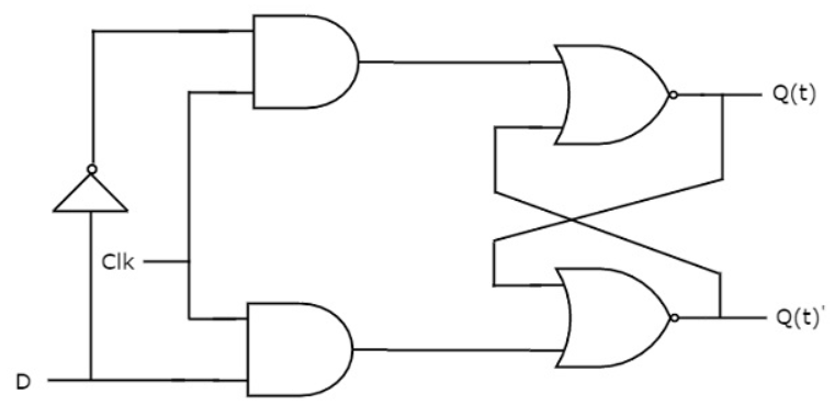
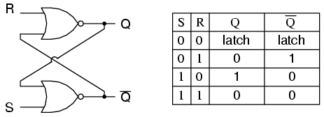
Neither of the pictures you posted are flip-flops, they are gated D-latches drawn differently. The two circuits are identical and are based off an SR latch.
Below is a pure SR NOR latch along with a state table and symbol.
![enter image description here]()
![enter image description here]()
By adding additional logic a D-latch is created.
![enter image description here]()
![enter image description here]()
In order to know the difference between a latch and a flip-flop you need to understand what they are.
A "latch" by definition is a memory element that does not have immunity to external feedback. In simpler terms, a latch is a feedback circuit that has two stable states (aka bistable multivibrator), '0' and '1', and can be used to store state information. Latches are created from combinatorial logic gates. Typically, a latch is asynchronously level-triggered; however, sometimes a latch requires a clock (CLK), in which case the latch is referred to as a "synchronous latch", and is equivalent to the gated D-latch circuits shown in both your pictures.
A "flip-flop" is by definition a two-stage latch in a master-slave configuration. Like a latch, a flip-flop is a circuit that has two stable states (aka bistable multivibrator), '0' and '1', and can be used to store information. Flip-flops are created by combining together two latch circuits to form one larger flip-flop circuit. The flip-flops are triggered on the edges of a signal, usually a clock.
Below is a picture of a D-Type flip-flop created by combining two SR NAND latch circuits.
![D-Type Flip-Flop]()
![enter image description here]()
The first latch is referred to as the "master", while the second latch is referred to as the "slave." Data (D) is latched on the rising edge of the clock (C).


