How does AutoCAD calculate end tangents for splines defined only by fit points?
Asked Answered
H

3

7

AutoCAD allows to store SPLINE entities in the DXF files defined only by fit points, the problem is, that such a spline definition has infinite numerical correct solutions and Autodesk does not provide the necessary information to calculate the required parameters from the given fit points.

tl;dr - The missing information are the estimated start- and end tangents in direction and magnitude for the input tangents to the global B-spline interpolation with end derivatives, can anyone help to calculate this values?

Complete source code on github.

I use BricsCAD for testing, but "Trueview 2020" shows the same results.

1. Scenario

Only fit points are given, using the global curve interpolation without any constraints to get a spline defined by control vertices:

# First spline defined by control vertices interpolated from given fit points
s = global_bspline_interpolation(points, degree=3)
msp.add_spline(dxfattribs={'color': 4, 'layer': 'Global Interpolation'}).apply_construction_tool(s)
# Second spline defined only by fit points as reference
spline = msp.add_spline(points, degree=3, dxfattribs={'layer': 'BricsCAD B-spline', 'color': 2})
doc.saveas(DIR / 'fit-points-only.dxf')

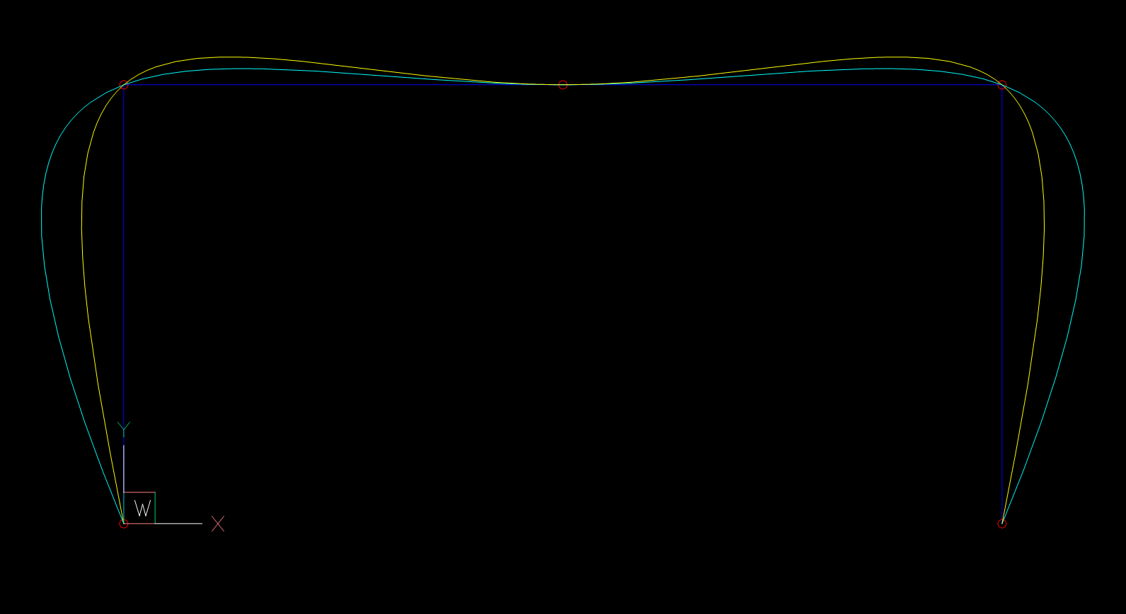
The Spline interpolated by BricsCAD from fit points does not match the spline defined by the interpolated control vertices:

Spline without constraints

2. Scenario

Beside the fit points I store also the start- and end tangent values in the DXF file. The interpolation is done by global curve interpolation with end derivatives (Piegl & Tiller: "The NURBS Book" - chapter 9.2.2).

I chose an arbitrary angle (100 degrees) as start- and end tangents, the tangent magnitude is estimated by the "Total chord length" method.

m1, m2 = estimate_end_tangent_magnitude(points, method='chord')
start_tangent = Vector.from_deg_angle(100) * m1
end_tangent = Vector.from_deg_angle(-100) * m2
# First spline defined by control vertices interpolated from given fit points and end-tangents
s = global_bspline_interpolation(points, degree=3, tangents=(start_tangent, end_tangent))
msp.add_spline(dxfattribs={'color': 4, 'layer': 'Global Interpolation'}).apply_construction_tool(s)
# Result matches the BricsCAD interpolation if fit points, start- and end
# tangents are stored explicit in the DXF file.
# Second spline defined by fit points as reference
spline = msp.add_spline(points, degree=3, dxfattribs={'layer': 'BricsCAD B-spline', 'color': 2})
# set explicit start- and end tangent as unit vectors
spline.dxf.start_tangent = Vector.from_deg_angle(100)
spline.dxf.end_tangent = Vector.from_deg_angle(-100)
doc.saveas(DIR / 'fit-points-and-tangents.dxf')

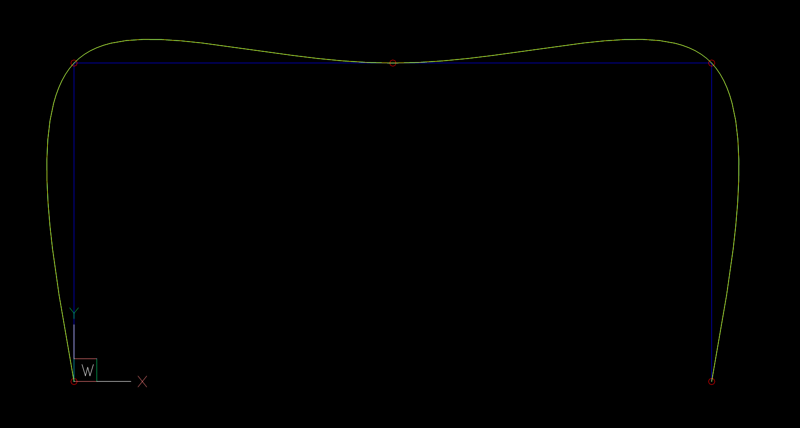
The Spline interpolated by BricsCAD now matches exactly the spline defined by the interpolated control vertices:

matching splines

Now I know the interpolation method is correct, all I need to render the same spline from fit points as BricsCAD are the end-tangents in direction and magnitude inferred from the fit points.

3. Scenario

I need the control vertices to render the B-spline, but start- and end tangents are not stored in the DXF file like in scenario 1. Estimation of start- and end tangents is required, best result by: "5 Point Interpolation" from "The NURBS Book", Piegl & Tiller

tangents = estimate_tangents(points, method='5-points')
# Estimated tangent angles: (108.43494882292201, -108.43494882292201) degree
m1, m2 = estimate_end_tangent_magnitude(points, method='chord')
start_tangent = tangents[0].normalize(m1)
end_tangent = tangents[-1].normalize(m2)
# First spline defined by control vertices interpolated from given fit points and end-tangents
s = global_bspline_interpolation(points, degree=3, tangents=(start_tangent, end_tangent))
msp.add_spline(dxfattribs={'color': 4, 'layer': 'Global Interpolation'}).apply_construction_tool(s)
# Second spline defined by fit points as reference, but without explicit start- and end 
# tangents to see if my estimations are correct.
msp.add_spline(points, degree=3, dxfattribs={'layer': 'BricsCAD B-spline', 'color': 2})
doc.saveas(DIR / 'tangents-estimated.dxf')

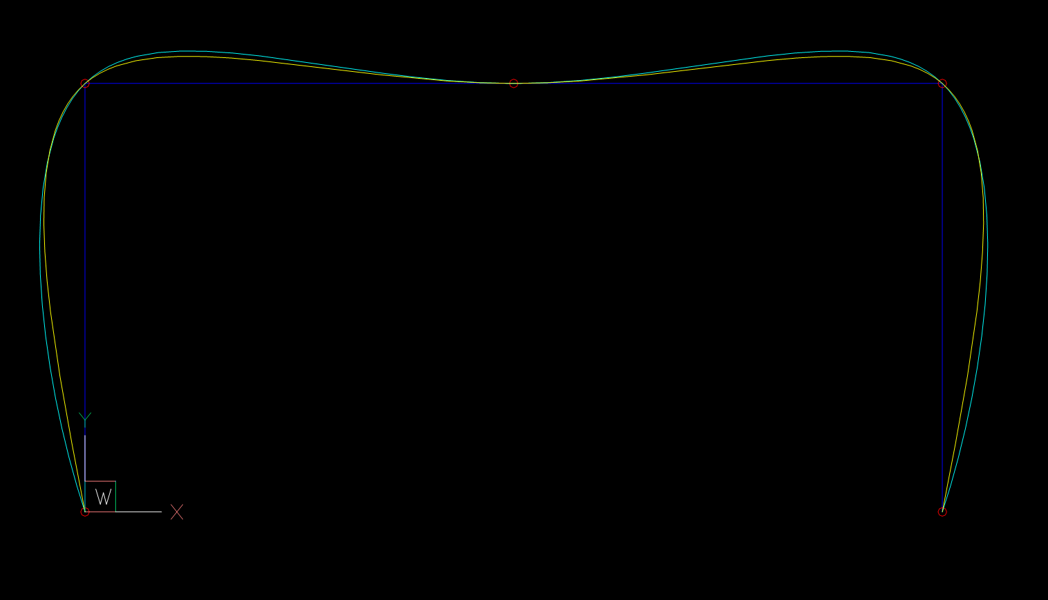
And surprise the estimations are not correct, BricsCAD spline has tangent angles of 101.0035408517495 and -101.0035408517495 degrees.

splines do not match again

And the really annoying part is, if I use the BricsCAD angles as input, the splines still does not match, so I assumed that the tangent magnitude estimation is different from scenario 2.

4. Theory Check

Following values are calculated from a DXF file saved by BricsCAD and SPLINE "Method" switched from "fit points" to "control vertices". From this data I calculated the tangent angles and also the magnitudes, tangent vector = 2nd control vertex - 1st control vertex

required_angle = 101.0035408517495  # angle of tangent vector in degrees
required_magnitude = m1 * 1.3097943444804256  # magnitude of tangent vector
start_tangent = Vector.from_deg_angle(required_angle, required_magnitude)
end_tangent = Vector.from_deg_angle(-required_angle, required_magnitude)
s = global_bspline_interpolation(points, degree=3, tangents=(start_tangent, end_tangent))
msp.add_spline(dxfattribs={'color': 4, 'layer': 'Global Interpolation'}).apply_construction_tool(s)
msp.add_spline(points, degree=3, dxfattribs={'layer': 'BricsCAD B-spline', 'color': 2})
doc.saveas(DIR / 'theory-check.dxf')

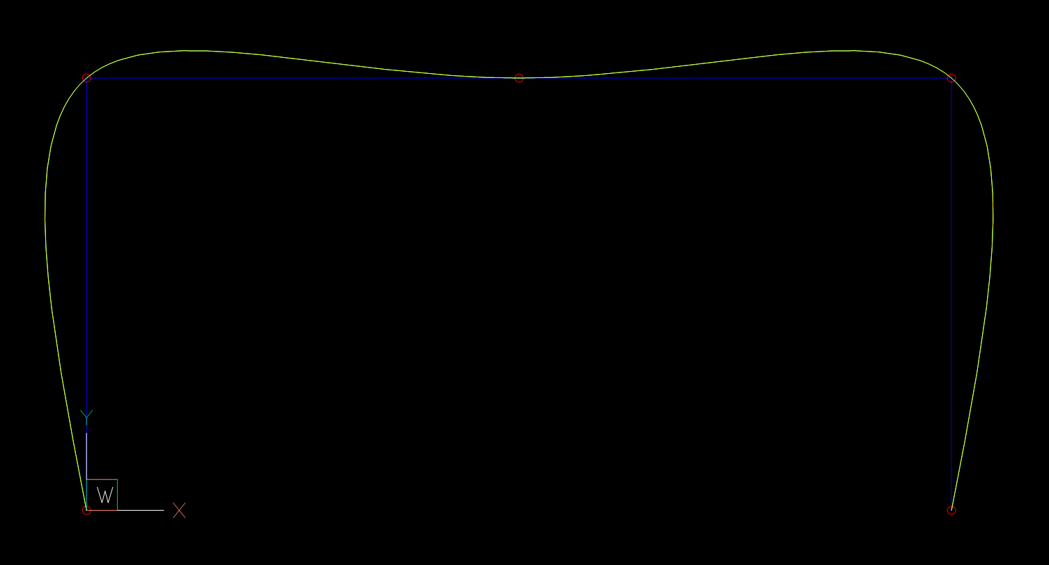
Now the splines match again:

now the splines match again

  1. If tangents are given (stored in DXF) the magnitude of the input tangents for the interpolation function is "total chord length".
  2. Without given tangents the magnitude is different, in this example: m1*1.3097943444804256, but it is not a constant factor.

The big question is: How to estimate the start- and end tangents in direction and magnitude like AutoCAD or BricsCAD for splines defined only by fit points?

Thanks in advance,

Manfred

Hoey answered 19/6, 2020 at 14:22 Comment(1)
I've wrestled from time to time with the way AutoCAD calculates some of their values, like with arcs and ellipses. This one is out of my league. Seems like it might possibly get a little traction on Math.SE, have you tried there also?Fard
Q
1

I had to face the same problem, and I found that if the tangent information is missing, they use a Cubic B-Spline interpolation of type natural. That is, they impose that the second derivative at the beginning and at the end of the curve is zero.

Quinonez answered 20/12, 2022 at 12:48 Comment(6)
Let me know if you need further details about the algorithm.Quinonez
Thank you! I know all splines from fit points are cubic B-splines and I have a function to generate a "natural" knot vector, but I have no idea how to integrate the second derivatives into the equation matrix. The bspline.py module shows how I added the end tangents to the equation according the "The NURBS Book" by Piegl & Tiller. Can you add more information?Hoey
BTW: I wrote the code for B-splines some time ago and I don't use linear algebra a lot, so please take that into account in your answer.Hoey
The algorithm to use is the A9.2 of the "The NURBS Book" by Piegl & Tiller within the 9.2.3 paragraph. But, in the second equation of 9.14 and the second of 9.15 P_1 and P_n-1 are not automatically known but must be determined as unknowns. You should impose that C''(0)=0 and C''(1)=0. You can find the formula for the second derivative of a Cubic Spline at the beginning and at the end on page 99 (equations 3.9 and 3.10). You need to implement the SolveTridiagonal algorithm but you need to add one row at the beginning and one row at the end on the matrix to take in account this new equations.Quinonez
Thank you again! It took a while to understand the solution, but it seem to work, at least least for this example.Hoey
It took me a long time too, but when I found out it was gratifying.Quinonez
H
1

The 3rd Scenario seems to be solved: SPLINE entities from fit points without given end tangents.

Applying a cubic Bézier curve interpolation seems to be the solution:

enter image description here

There is no visual difference between the BricsCAD/AutoCAD and the ezdxf SPLINE.

The conversion from cubic Bèzier curve to a cubic SPLINE is described here on math.stackexchange.com, and implemented here in ezdxf v0.16 and the source code for the cubic Bézier curve interpolation is here.

This works only for cubic B-splines (the most common used B-spline), and BricsCAD/AutoCAD allow only a degree of 2 or 3 for SPLINE entities defined only by fit points. The only thing missing is an interpolation of quadratic B-splines as quadratic Bézier curves.

Further research showed that quadratic B-splines defined by fit points are loaded into BricsCAD/AutoCAD as cubic B-splines. Addition to the statement above:

BricsCAD and AutoCAD only use a degree of 3 for SPLINE entities defined only by fit points.

The solution for a B-spline without given end tangents is a cubic Bèzier interpolation, no end tangent calculation is needed.

UPDATE: not a solution

Sadly this all works just for small simple B-splines:

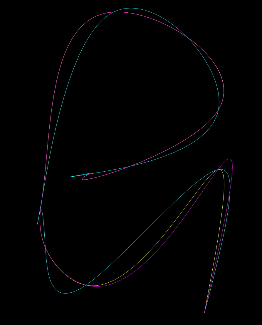
Comlex Spline

  • yellow: SPLINE by BricsCAD
  • cyan: Bèzier curve interpolation
  • magenta: global curve interpolation

The global curve interpolation is the much better solution than the Bèzier curve interpolation. It diverges just at the beginning of the B-spline, where the Bèzier curve interpolation totally fails.

The search for the AutoCAD end tangents continues ...

Hoey answered 25/2, 2021 at 4:50 Comment(0)
Q
1

I had to face the same problem, and I found that if the tangent information is missing, they use a Cubic B-Spline interpolation of type natural. That is, they impose that the second derivative at the beginning and at the end of the curve is zero.

Quinonez answered 20/12, 2022 at 12:48 Comment(6)
Let me know if you need further details about the algorithm.Quinonez
Thank you! I know all splines from fit points are cubic B-splines and I have a function to generate a "natural" knot vector, but I have no idea how to integrate the second derivatives into the equation matrix. The bspline.py module shows how I added the end tangents to the equation according the "The NURBS Book" by Piegl & Tiller. Can you add more information?Hoey
BTW: I wrote the code for B-splines some time ago and I don't use linear algebra a lot, so please take that into account in your answer.Hoey
The algorithm to use is the A9.2 of the "The NURBS Book" by Piegl & Tiller within the 9.2.3 paragraph. But, in the second equation of 9.14 and the second of 9.15 P_1 and P_n-1 are not automatically known but must be determined as unknowns. You should impose that C''(0)=0 and C''(1)=0. You can find the formula for the second derivative of a Cubic Spline at the beginning and at the end on page 99 (equations 3.9 and 3.10). You need to implement the SolveTridiagonal algorithm but you need to add one row at the beginning and one row at the end on the matrix to take in account this new equations.Quinonez
Thank you again! It took a while to understand the solution, but it seem to work, at least least for this example.Hoey
It took me a long time too, but when I found out it was gratifying.Quinonez
G
0

The SPLINE entity can have optional group codes 12,22,32 for start tangent x,y,z and 13,23,33 for end tangent x,y,z. I've checked source code of netDxf project, and it follows that if fit points only are used to define the spline, then start and end tangent values are to be specified.

From AutoCAD 2012 DXF Reference for SPLINE entity:

12 Start tangent—may be omitted (in WCS) DXF: X value; APP: 3D point

22, 32 DXF: Y and Z values of start tangent—may be omitted (in WCS)

13 End tangent—may be omitted (in WCS) DXF: X value; APP: 3D point

23, 33 DXF: Y and Z values of end tangent—may be omitted (in WCS)

We created a few DXF files yesterday with my colleague in Autocad 2020, including fit-point splines. After export to DXF, the splines were defined by control points and knots. So I have a guess that fit points is something obsolete or UI-only.

Ganof answered 2/9, 2020 at 7:48 Comment(1)
Thank you! But the reason for this question was to recreate the same spline as AutoCAD or BricsCAD, if the end tangents are not given/specified. The problem is solved for the case of given end tangents. You will have the same problem if you get DXF files from other sources than AutoCAD (e.g. ezdxf users ;-), and a SPLINE defined only by fit points without end tangents is a valid DXF construct.Hoey

© 2022 - 2024 — McMap. All rights reserved.