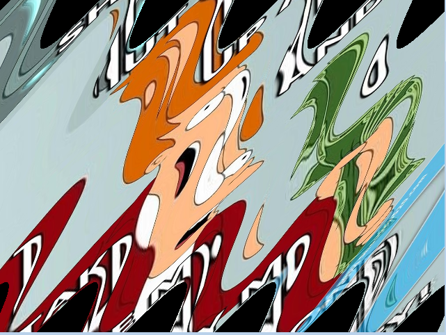
OK I tried to recreate your effect so I used this as texture:
![texture]()
I took your image and resize it to 512x512 so it is power of 2 fill the border with black. As you do not share Vertex shader I created my own. The GL is rendering single quad <-1,+1> without texture coordinates or matrices only glVertex2f() with single 2D texture binded to unit 0. I slightly rewrite your fragment to match the output. Also I added tx,ty uniforms to easily animate the effect with mouse position <0,1> Here are the shaders first vertex:
// Vertex
varying vec2 v_texCoord;
void main()
    {
    v_texCoord=gl_Vertex.xy;
    gl_Position=gl_Vertex;
    }
And then fragment:
// Fragment
varying vec2 v_texCoord;        // holds the Vertex position <-1,+1> !!!
uniform sampler2D s_baseMap;    // used texture unit
uniform float tx,ty;            // x,y waves phase

vec2 SineWave( vec2 p )
    {
    // convert Vertex position <-1,+1> to texture coordinate <0,1> and some shrinking so the effect dont overlap screen
    p.x=( 0.55*p.x)+0.5;
    p.y=(-0.55*p.y)+0.5;
    // wave distortion
    float x = sin( 25.0*p.y + 30.0*p.x + 6.28*tx) * 0.05;
    float y = sin( 25.0*p.y + 30.0*p.x + 6.28*ty) * 0.05;
    return vec2(p.x+x, p.y+y);
    }

void main()
    {
    gl_FragColor = texture2D(s_baseMap,SineWave(v_texCoord));
    }
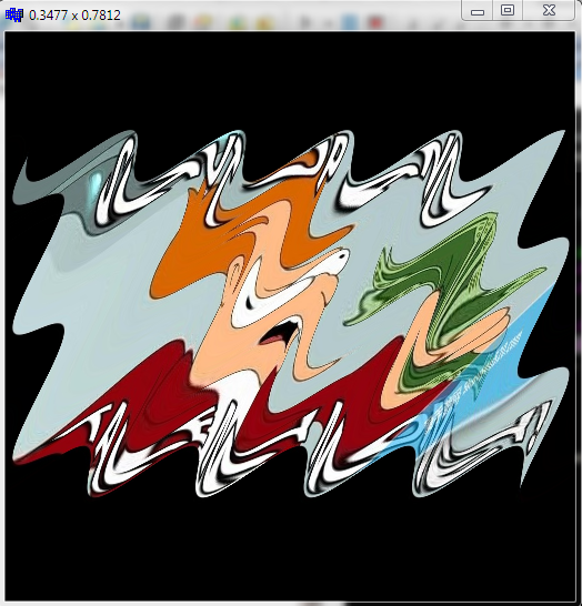
This is output for tx=0.3477,ty=0.7812 which visually more or less matches your example:
![output]()
As you can see I added few terms into the sin waves so it got also skew distortion.
If you have the v_texCoord already in range <0,1> then ignore the
    p.x=( 0.55*p.x)+0.5;
    p.y=(-0.55*p.y)+0.5;
or rewrite it to (so the shrink and coefficients stay as should)
    p.x=(1.1*p.x)-0.05;
    p.y=(1.1*p.y)-0.05;
If you use different texture (not mine) then you need to rescale all the coefficients.
[edit1] coefficients meaning
first I started with yours:
float x = sin( 10.0*p.y) * 0.15;
float y = sin( 10.0*p.x) * 0.15;
The 0.15 is wave amplitude which seems to be too big so I lower it to 0.05. Then 10.0 is frequency the bigger the number the more waves along axis will be. By pure trial&error I determine they should be 30.0 for y axis and 25.0 for x axis so the number of waves matches your desired output.
float x = sin( 25.0*p.y) * 0.05;
float y = sin( 30.0*p.x) * 0.05;
After this I spotted that the waves should be a bit skewed so I add dependency on the other axis too after some tweaking found out this equation:
float x = sin( 25.0*p.y + 30.0*p.x) * 0.05;
float y = sin( 25.0*p.y + 30.0*p.x) * 0.05;
where both coefficients are the same in between axises (weird but working I was expecting I would need to have different coefficients between axises). After this is just a matter of finding the correct phase for each axis so I add phase shift controlled by mouse position (tx,ty) <0.0,1.0> so I got the final:
float x = sin( 25.0*p.y + 30.0*p.x + 6.28*tx) * 0.05;
float y = sin( 25.0*p.y + 30.0*p.x + 6.28*ty) * 0.05;
Then I play with mouse (printing its position) until I got close enough to match your desired output which was when tx=0.3477,ty=0.7812 so you can hard-code
float x = sin( 25.0*p.y + 30.0*p.x + 6.28*0.3477) * 0.05;
float y = sin( 25.0*p.y + 30.0*p.x + 6.28*0.7812) * 0.05;


xaxis you are computingy = sin( w*p.x + t) * A;so try to distort also thexlikex = sin( w*p.y + t) * A;and may be play a bit with constants (having separate constants forxand fory). – Superb