How do you link up the lollipops using Enterprise Architect - Component Diagram (assembly relationship)
Asked Answered
I

2

8

I am busy putting together a component diagram using EA by Sparx System (version 15.1).

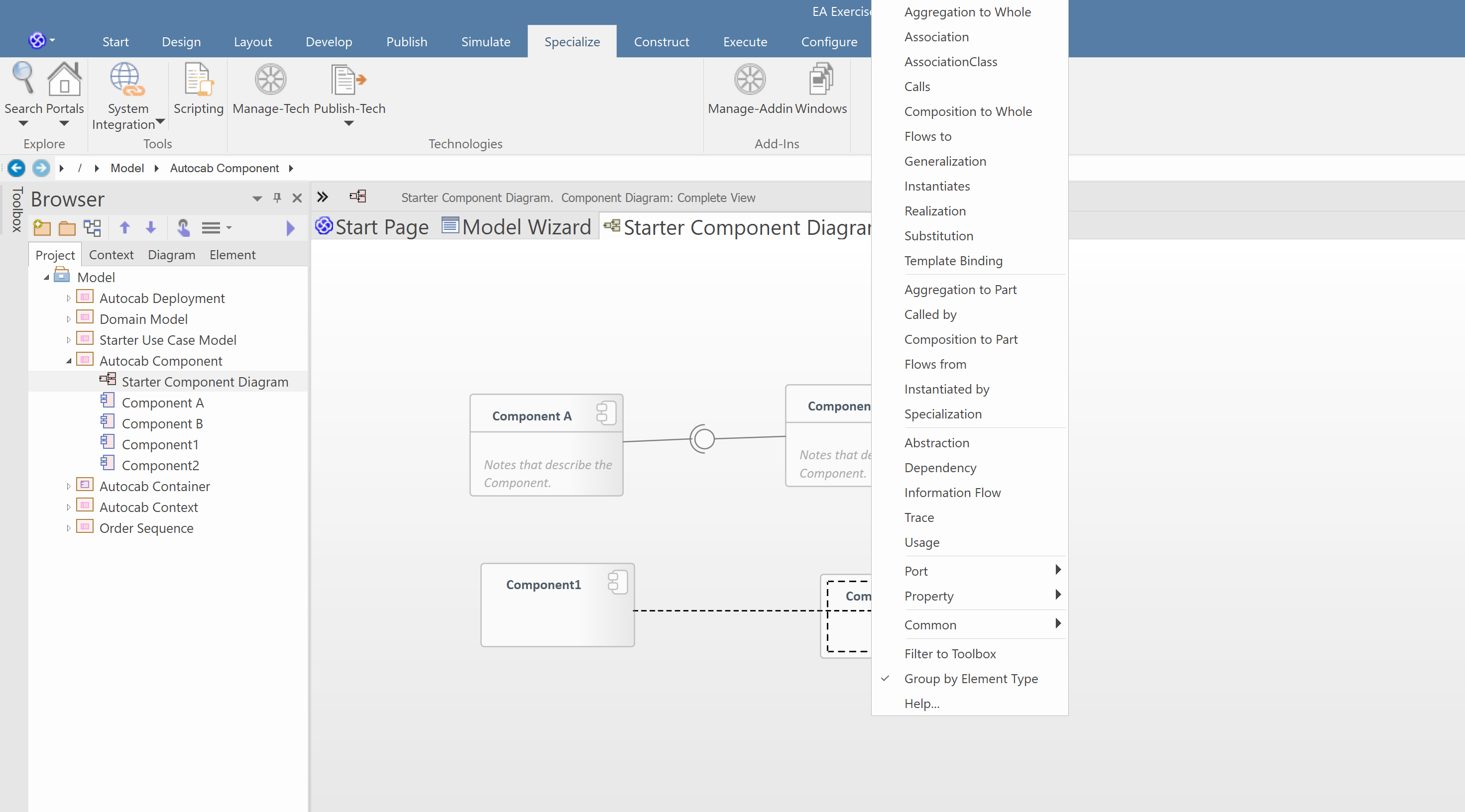
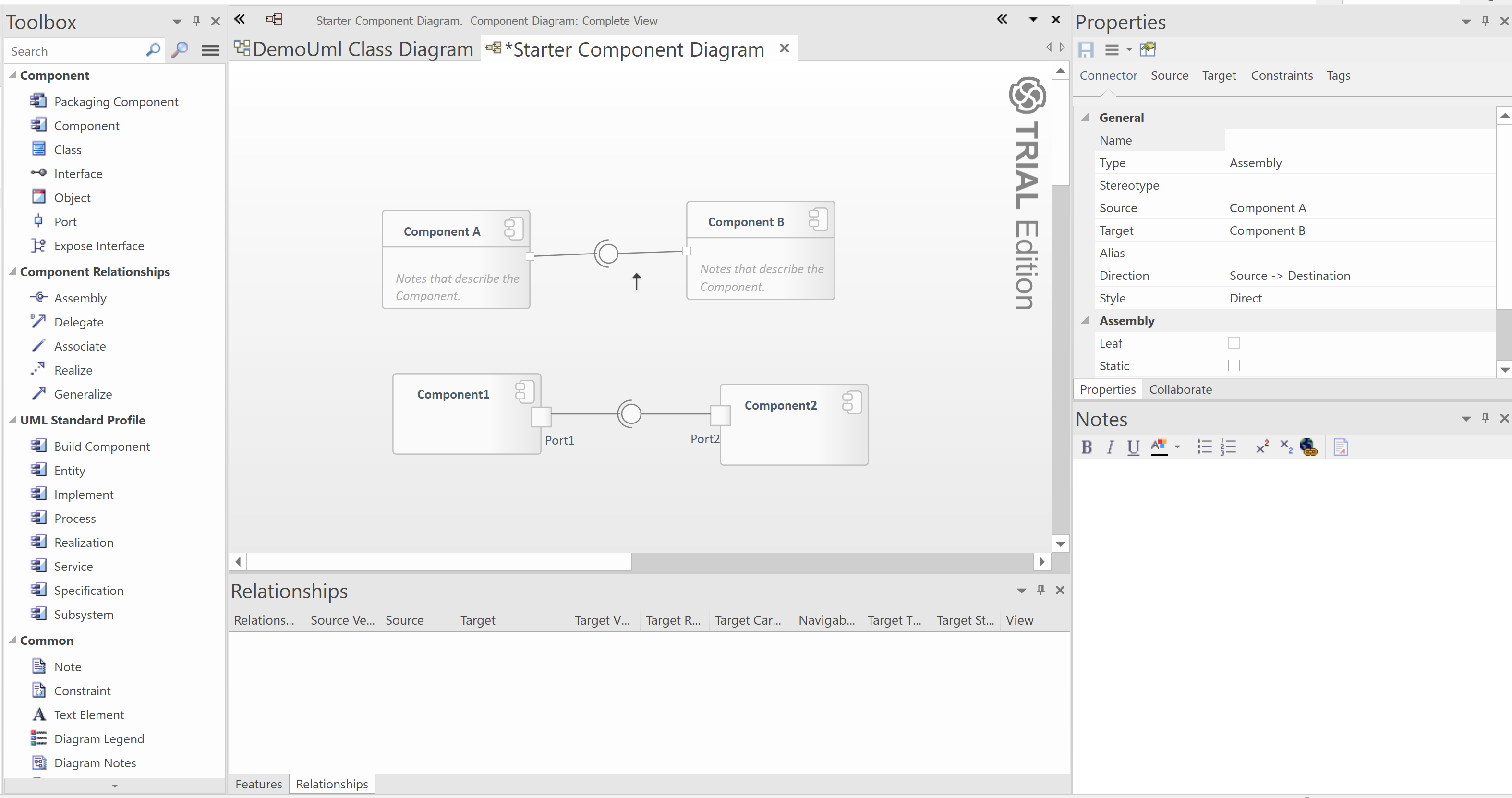
I would like to achieve the top diagram (component A and B). However when I setup an assembly relationship you need to configure a required and a provided interface (with / without port). I have tried a few options (C & D / E & F) but am unable to link the lolipops like A & B.

Any experience here would be useful how to achieve this. The EA documentation is very poor. enter image description here

enter image description here

enter image description here

Ine answered 20/4, 2020 at 21:2 Comment(1)
Yes, their docs suck :-/Zillion
C
10

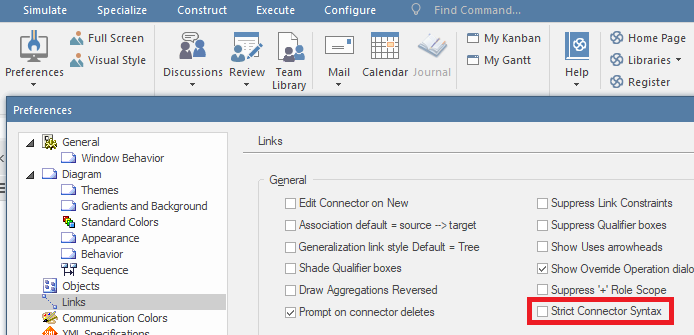
If you want to add an assembly connector between components, you need to disable Strict Connector Syntax in Start > Desktop > Preferences > Links > Strict Connector Syntax:

enter image description here

Cannady answered 25/6, 2020 at 8:31 Comment(1)
You save my world.Damiandamiani
Z
4

The basic issue (unfortunately) is a constraint of the UML 2.5 metamodel (which was not present in 2.1.1). This allows assembly connectors only between Property metaclasses (being Port and ExtensionEnd). So when you're doing the above from a port to another port you will see the assembly in the quick linker.

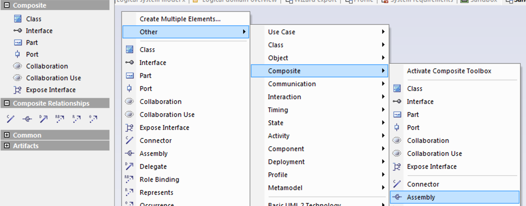
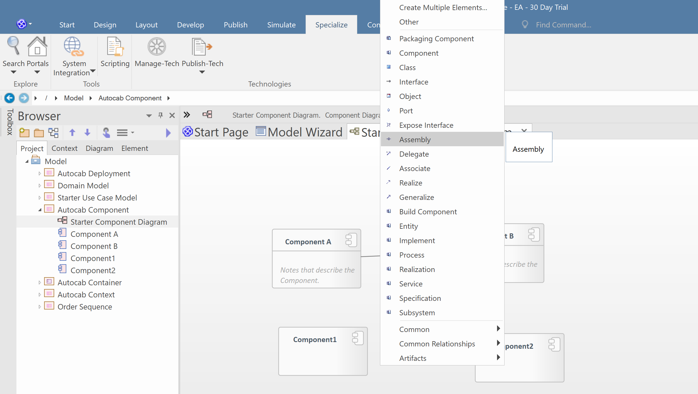
If you want assmeblies between components you have to use them explicitely from the toolbox.

enter image description here

(Either show the Composite toolbox or go via the context menu)

I'm using them during early design since I know that I'll replace them later when I got the real interfaces. However, one must know that such a model is not compliant to the UML standard. But who cares about standards if you can make your own ;-) ?


Original answer (probably still usefull)

The top is just an assembly connector. Use that for a first sketch when you have no details about interfaces.

The middle one is the preferred one in design. You draw a dependency relation from the required to the provided IF (pointing left to right).

The lower one is not ok. You use an assembly in conjunction with a real provided IF with the assembly being oriented the wrong way. I suggest to use that assembly only in an early design stage and once you get the IF right (sockets and lollipops) to connect these with a dependency.


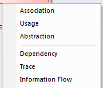
Since EA behave consistently inconsistent: In order to create an assembly you can not use the quick linker. Dragging from one component to another just offers

enter image description here

Rather with the component diagram focus hit the space bar and you get the toolbox

enter image description here

Select the assembly connector (you could as well have the toolbox window open and select the connector there, but I prefer this way). Now you can drag from source to target component.
Zillion answered 20/4, 2020 at 22:16 Comment(12)
I hope you can guide my thinking here. I setup two components and then try dragging the assembly connector (under toolbox / component relationship) from the source component to the target component. However during the process I am required to indicate what type of relationship is required (association, generatlisation, etc.). There is no option for assembly. What am I doing wrong?Ine
Thanks for your input here. I initially tried your approach before logging the question. I have included screenshots of the context menu which is shown over the source and target. There is no option for the target to select the assembly connector. I have also tried deselecting the strict UML connector option under preferences. This does not help. Can you think of any other options here.Ine
I agree with you. I think this is a bug. I will open up a ticket and hope for the best. Thanks for your support here. Really appreciate it.Ine
I don't think it's a bug. Looking at the UML metamodel I see that a Connector (which is the metatype of an assembly) has two ConnectoEnd. Those have an attribute definingProperty of type Property. So connectors are only allowed between Properties (ports) and not between Components. EA enforces this now correctly. The quicklinker allows for Assembly connectors between ports on Components.Buckthorn
@GeertBellekens Yes, of course. A pity though since I found assembly connectors especially usefull when sketching things. Will make another update.Zillion
The funny thing is that even on the Sparx help page the example is wrong: sparxsystems.com/enterprise_architect_user_guide/15.1/…Buckthorn
@GeertBellekens Well, about their Help - that's another story (see the OP's last sentencs and my comment above). I fixed my answer. Thanks!Zillion
@GeertBellekens But wait, their UML 2.1.1 citation is correct. So the metamodel must have changed? Just looked it up. Answer: Yes.Zillion
Do I understand you correctly, that you propose that assembly connector is only allowed between ports? How come does EA Starter Component Diagram have a direct assembly connector between components then? It should be achievable somehow, but I'm also struggling with this.Cannady
@Cannady I don't propose that. UML 2.5 imposed that. That's what the standard says. Using assemblies on other elements than Port/ExtensionEnd is syntactically wrong.Zillion
@qwerty_so, thanks for clarifying. Nevertheless, can you figure out why/how is the direct assembly connector between components A and B possible in EA Starter Component Diagram (as shown in original question)? It is OK for me that it is non-standard, I just want to create these connections myself as well.Cannady
@qwerty_so, I asked from their support meanwhile, see my answer below.Cannady

© 2022 - 2024 — McMap. All rights reserved.