you should also add the input in vector form so we can test on your data ... I would approach like this:
- find center of axis aligned bbox
O(n)
compute max distance in each angle O(n)
just create table for enough m angles (like 5 deg step so m = 360/5) where for each angle section you remember max distant point distance only.
compute max perpendicular distance for each rotation O(m^2)
so for each angle section compute value that is:
value[actual_section] = max(distance[i]*cos(section_angle[i]-section_angle[actual_section]))
where i covers +/- 90 deg around actual section angle so now you got max perpendicular distances for each angle...
pick best solution O(m)
so look all rotations from 0 to 90 degrees and remember the one that has minimal OBB area. Just to be sure the OBB is aligned to section angle and size of axises is the value of that angle and all the 90 deg increments... around center
![sketch]()
This will not result in optimal solution but very close to it. To improve precision you can use more angle sections or even recursively search around found solution with smaller and smaller angle step (no need to compute the other angle areas after first run.
[Edit1]
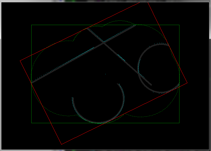
I tried to code this in C++ as proof of concept and use your image (handled as set of points) as input so here the result so you got something to compare to (for debugging purposes)
![example]()
gray are detected points from your image, green rectangle is axis aligned BBox the red rectangle is found OBBox. The aqua points are found max distance per angle interval and green dots are max perpendicular distance for +/-90deg neighbor angle intervals. I used 400 angles and as you can see the result is pretty close ... 360/400 deg accuracy so this approach works well ...
Here C++ source:
//---------------------------------------------------------------------------
struct _pnt2D
    {
    double x,y;
    // inline
    _pnt2D()    {}
    _pnt2D(_pnt2D& a)   { *this=a; }
    ~_pnt2D()   {}
    _pnt2D* operator = (const _pnt2D *a) { *this=*a; return this; }
    //_pnt2D* operator = (const _pnt2D &a) { ...copy... return this; }
    };
struct _ang
    {
    double  ang;    // center angle of section
    double  dis;    // max distance of ang section
    double pdis;    // max perpendicular distance of +/-90deg section
    // inline
    _ang()  {}
    _ang(_ang& a)   { *this=a; }
    ~_ang() {}
    _ang* operator = (const _ang *a) { *this=*a; return this; }
    //_ang* operator = (const _ang &a) { ...copy... return this; }
    };
const int    angs=400;  // must be divisible by 4
const int    angs4=angs>>2;
const double dang=2.0*M_PI/double(angs);
const double dang2=0.5*dang;
_ang ang[angs];
List<_pnt2D> pnt;
_pnt2D bbox[2],obb[4],center;
//---------------------------------------------------------------------------
void compute_OBB()
    {
    _pnt2D ppp[4];
    int i,j; double a,b,dx,dy;
    _ang *aa,*bb;
    _pnt2D p,*pp; DWORD *q;
    // convert bmp -> pnt[]
    pnt.num=0;
    Graphics::TBitmap *bmp=new Graphics::TBitmap;
    bmp->LoadFromFile("in.bmp");
    bmp->HandleType=bmDIB;
    bmp->PixelFormat=pf32bit;
    for (p.y=0;p.y<bmp->Height;p.y++)
     for (q=(DWORD*)bmp->ScanLine[int(p.y)],p.x=0;p.x<bmp->Width;p.x++)
      if ((q[int(p.x)]&255)<20)
       pnt.add(p);
    delete bmp;
    // axis aligned bbox
    bbox[0]=pnt[0];
    bbox[1]=pnt[0];
    for (pp=pnt.dat,i=0;i<pnt.num;i++,pp++)
        {
        if (bbox[0].x>pp->x) bbox[0].x=pp->x;
        if (bbox[0].y>pp->y) bbox[0].y=pp->y;
        if (bbox[1].x<pp->x) bbox[1].x=pp->x;
        if (bbox[1].y<pp->y) bbox[1].y=pp->y;
        }
    center.x=(bbox[0].x+bbox[1].x)*0.5;
    center.y=(bbox[0].y+bbox[1].y)*0.5;
    // ang[] table init
    for (aa=ang,a=0.0,i=0;i<angs;i++,aa++,a+=dang)
        {
        aa->ang=a;
        aa-> dis=0.0;
        aa->pdis=0.0;
        }
    // ang[].dis
    for (pp=pnt.dat,i=0;i<pnt.num;i++,pp++)
        {
        dx=pp->x-center.x;
        dy=pp->y-center.y;
        a=atan2(dy,dx);
        j=floor((a/dang)+0.5); if (j<0) j+=angs; j%=angs;
        a=(dx*dx)+(dy*dy);
        if (ang[j].dis<a) ang[j].dis=a;
        }
    for (aa=ang,i=0;i<angs;i++,aa++) aa->dis=sqrt(aa->dis);
    // ang[].adis
    for (aa=ang,i=0;i<angs;i++,aa++)
     for (bb=ang,j=0;j<angs;j++,bb++)
        {
        a=fabs(aa->ang-bb->ang);
        if (a>M_PI) a=(2.0*M_PI)-a;
        if (a<=0.5*M_PI)
            {
            a=bb->dis*cos(a);
            if (aa->pdis<a) aa->pdis=a;
            }
        }
    // find best oriented bbox (the best angle is ang[j].ang)
    for (b=0,j=0,i=0;i<angs;i++)
        {
        dx =ang[i].pdis; i+=angs4; i%=angs;
        dy =ang[i].pdis; i+=angs4; i%=angs;
        dx+=ang[i].pdis; i+=angs4; i%=angs;
        dy+=ang[i].pdis; i+=angs4; i%=angs;
        a=dx*dy; if ((b>a)||(i==0)) { b=a; j=i; }
        }
    // compute endpoints for OBB
    i=j;
    ppp[0].x=ang[i].pdis*cos(ang[i].ang);
    ppp[0].y=ang[i].pdis*sin(ang[i].ang); i+=angs4; i%=angs;
    ppp[1].x=ang[i].pdis*cos(ang[i].ang);
    ppp[1].y=ang[i].pdis*sin(ang[i].ang); i+=angs4; i%=angs;
    ppp[2].x=ang[i].pdis*cos(ang[i].ang);
    ppp[2].y=ang[i].pdis*sin(ang[i].ang); i+=angs4; i%=angs;
    ppp[3].x=ang[i].pdis*cos(ang[i].ang);
    ppp[3].y=ang[i].pdis*sin(ang[i].ang); i+=angs4; i%=angs;
    obb[0].x=center.x+ppp[0].x+ppp[3].x;
    obb[0].y=center.y+ppp[0].y+ppp[3].y;
    obb[1].x=center.x+ppp[1].x+ppp[0].x;
    obb[1].y=center.y+ppp[1].y+ppp[0].y;
    obb[2].x=center.x+ppp[2].x+ppp[1].x;
    obb[2].y=center.y+ppp[2].y+ppp[1].y;
    obb[3].x=center.x+ppp[3].x+ppp[2].x;
    obb[3].y=center.y+ppp[3].y+ppp[2].y;
    }
//---------------------------------------------------------------------------
I used mine dynamic list template so:
List<double> xxx; is the same as double xxx[];
xxx.add(5); adds 5 to end of the list
xxx[7] access array element (safe)
xxx.dat[7] access array element (unsafe but fast direct access)
xxx.num is the actual used size of the array
xxx.reset() clears the array and set xxx.num=0
xxx.allocate(100) preallocate space for 100 items
You can ignore the // convert bmp -> pnt[] VCL part as you got your data already.
I recommend to also take a look at my:


