Better shading on BW display while rendering filled surfaces
Asked Answered
S

2

2

Prologue

I finally got around HW incompatibility between AT32UC3xxxxx and SSD1306 OLED I2C display (both have HW bugs making them incompatible) allowing me to use HW I2C at 400KBaud (~26.6ms per frame). So I decided to rewrite my old driver for this LCD to make advantage of the new speed by adding also filled surfaces (triangles,quads) instead of just lines and patterned lines (which I already implemented).

The problem is the display is 128x64 pixels but no colors or shades of gray just BW on/off

So in order to for example render rotating cube I need to distinguish the surfaces somehow. I was thinking about randomized filling pattern where surface is filled to some percentage instead of color.

Here my current code (Whole lib but without bugs its working as should):

LCD_SSD1306_I2C.h

//------------------------------------------------------------------------------------------
//--- SSD1306 I2C OLED LCD driver ver 2.000 ------------------------------------------------
//------------------------------------------------------------------------------------------
#ifndef _LCD_SSD1306_I2C_h
#define _LCD_SSD1306_I2C_h
//------------------------------------------------------------------------------------------
#define SSD1306_SETCONTRAST 0x81
#define SSD1306_DISPLAYALLON_RESUME 0xA4
#define SSD1306_DISPLAYALLON 0xA5
#define SSD1306_NORMALDISPLAY 0xA6
#define SSD1306_INVERTDISPLAY 0xA7
#define SSD1306_DISPLAYOFF 0xAE
#define SSD1306_DISPLAYON 0xAF
#define SSD1306_SETDISPLAYOFFSET 0xD3
#define SSD1306_SETCOMPINS 0xDA
#define SSD1306_SETVCOMDETECT 0xDB
#define SSD1306_SETDISPLAYCLOCKDIV 0xD5
#define SSD1306_SETPRECHARGE 0xD9
#define SSD1306_SETMULTIPLEX 0xA8
#define SSD1306_SETLOWCOLUMN 0x00
#define SSD1306_SETHIGHCOLUMN 0x10
#define SSD1306_SETSTARTLINE 0x40
#define SSD1306_MEMORYMODE 0x20
#define SSD1306_COLUMNADDR 0x21
#define SSD1306_PAGEADDR   0x22
#define SSD1306_COMSCANINC 0xC0
#define SSD1306_COMSCANDEC 0xC8
#define SSD1306_SEGREMAP 0xA0
#define SSD1306_CHARGEPUMP 0x8D
#define SSD1306_SWITCHCAPVCC 0x2
// Scrolling #defines
#define SSD1306_ACTIVATE_SCROLL 0x2F
#define SSD1306_DEACTIVATE_SCROLL 0x2E
#define SSD1306_SET_VERTICAL_SCROLL_AREA 0xA3
#define SSD1306_RIGHT_HORIZONTAL_SCROLL 0x26
#define SSD1306_LEFT_HORIZONTAL_SCROLL 0x27
#define SSD1306_VERTICAL_AND_RIGHT_HORIZONTAL_SCROLL 0x29
#define SSD1306_VERTICAL_AND_LEFT_HORIZONTAL_SCROLL 0x2A
//------------------------------------------------------------------------------------------
//#define I2C_send(adr,buf,siz){}
//------------------------------------------------------------------------------------------
#ifndef _brv8_tab
#define _brv8_tab
static const U8 brv8[256] =     // 8 bit bit reversal
    {
    0,128,64,192,32,160,96,224,16,144,80,208,48,176,112,240,8,136,72,200,40,168,104,232,24,152,
    88,216,56,184,120,248,4,132,68,196,36,164,100,228,20,148,84,212,52,180,116,244,12,140,76,204,
    44,172,108,236,28,156,92,220,60,188,124,252,2,130,66,194,34,162,98,226,18,146,82,210,50,178,
    114,242,10,138,74,202,42,170,106,234,26,154,90,218,58,186,122,250,6,134,70,198,38,166,102,230,
    22,150,86,214,54,182,118,246,14,142,78,206,46,174,110,238,30,158,94,222,62,190,126,254,1,129,
    65,193,33,161,97,225,17,145,81,209,49,177,113,241,9,137,73,201,41,169,105,233,25,153,89,217,57,
    185,121,249,5,133,69,197,37,165,101,229,21,149,85,213,53,181,117,245,13,141,77,205,45,173,109,
    237,29,157,93,221,61,189,125,253,3,131,67,195,35,163,99,227,19,147,83,211,51,179,115,243,11,139,
    75,203,43,171,107,235,27,155,91,219,59,187,123,251,7,135,71,199,39,167,103,231,23,151,87,215,55,
    183,119,247,15,143,79,207,47,175,111,239,31,159,95,223,63,191,127,255
    };
#endif
//------------------------------------------------------------------------------------------
class LCD_SSD1306_I2C           // max 96 lines
    {
public:
    // screen
    int adr;                    // I2C adr
    int xs,ys,sz;               // resoluiton
    U8 _scr[((128*96)>>3)+1];   // screen buffer
    U8 *scr;
    U8 *pyx[96];                // scan lines
    // pattern
    U32 pat,pat_m,pat_b;        // binary pattern,max used bit mask,actual bit mask
    // filling
    U32 seed;
    int bufl[96];
    int bufr[96];

    // system api
    void init(int _adr,int _xs,int _ys);                    // initialize LCD: I2C_adr,xs,ys
    void _command(U8 cmd);                                  // *internal* do not cal it (sends command to LCD over I2C)
    void rfsscr();                                          // copy actual screen buffer to LCD (by I2C)
    // gfx rendering col = <0,1>
    void clrscr();                                          // clear screen buffer
    void rotate(int ang);                                   // rotate 180 deg
    void pixel(int x,int y,bool col);                       // set/res pixel
    bool pixel(int x,int y);                                // get pixel
    void line(int x0,int y0,int x1,int y1,bool col);        // line
    void triangle(int x0,int y0,int x1,int y1,int x2,int y2,bool col);// triangle
    void quad(int x0,int y0,int x1,int y1,int x2,int y2,int x3,int y3,bool col);
    void rect(int x0,int y0,int x1,int y1,bool col);        // rectangle using diagonal points
    // patern rendering
    void pat_set(char *s);                                  // set binary pattern from bianry number string MSB renders first
    void pat_beg();                                         // set pattern state to start of pattern
    void pat_line(int x0,int y0,int x1,int y1,bool col);
    void pat_triangle(int x0,int y0,int x1,int y1,int x2,int y2,bool col);
    void pat_quad(int x0,int y0,int x1,int y1,int x2,int y2,int x3,int y3,bool col);
    void pat_rect(int x0,int y0,int x1,int y1,bool col);
    // filled polygons col = <0,255>
    void _fill_line(int x0,int y0,int x1,int y1);           // *internal* do not call it (render line into bufl/bufr)
    void _fill_seed();                                      // *internal* do not call it (reset seed)
    U8   _fill_rand();                                      // *internal* do not call it (get pseudo random number)
    void fill_triangle(int x0,int y0,int x1,int y1,int x2,int y2,U8 col);
    void fill_quad(int x0,int y0,int x1,int y1,int x2,int y2,int x3,int y3,U8 col);
    // text rendering
    void prnchr(int x,int y,char c);                        // render char at x,y (y is rounded to multiple of 8)
    void prntxt(int x,int y,const char *txt);               // render text at x,y (y is rounded to multiple of 8)
    };
//------------------------------------------------------------------------------------------
void LCD_SSD1306_I2C::_command(U8 cmd)
    {
    U8 buf[2]=
        {
        0x00,       // 0x40 data/command
        cmd,
        };
    I2C_send(adr,buf,2);
    }
//------------------------------------------------------------------------------------------
void LCD_SSD1306_I2C::init(int _adr,int _xs,int _ys)
    {
    int y;
    adr=_adr;
    xs=_xs;
    ys=_ys;
    sz=xs*(ys>>3);
    const bool _external_Vcc=false;
    // VRAM buffer
    scr=_scr+1;                                         // skip first Byte (VRAM/command selection)
    for (y=0;y<ys;y++) pyx[y]=scr+((y>>3)*xs);          // scanlines for fast direct pixel access
    clrscr();
    // Init sequence
    U8 comPins = 0x02;
    U8 contrast = 0x8F;
         if((xs == 128) && (ys == 32)) { comPins = 0x02; contrast = 0x8F; }
    else if((xs == 128) && (ys == 64)) { comPins = 0x12; contrast = (_external_Vcc) ? 0x9F : 0xCF; }
    else if((xs ==  96) && (ys == 16)) { comPins = 0x02; contrast = (_external_Vcc) ? 0x10 : 0xAF; }
    else {} // Other screens
    static U8 init0[27]=
        {
        0x00,                                           // commands
        SSD1306_DISPLAYOFF,                             // 0xAE
        SSD1306_SETDISPLAYCLOCKDIV,0x80,                // 0xD5
        SSD1306_SETMULTIPLEX,ys-1,                      // 0xA8
        SSD1306_SETDISPLAYOFFSET,0x00,                  // 0xD3 no offset
        SSD1306_SETSTARTLINE | 0x0,                     // line 0
        SSD1306_CHARGEPUMP,(_external_Vcc)?0x10:0x14,   // 0x8D
        SSD1306_MEMORYMODE,0x00,                        // 0x20 horizontal (scanlines)
        SSD1306_SEGREMAP | 0x1,
        SSD1306_COMSCANDEC,
        SSD1306_SETCOMPINS,comPins,
        SSD1306_SETCONTRAST,contrast,
        SSD1306_SETPRECHARGE,(_external_Vcc)?0x22:0xF1, // 0xd9
        SSD1306_SETVCOMDETECT,0x40,                     // 0xDB
        SSD1306_DISPLAYALLON_RESUME,                    // 0xA4
        SSD1306_NORMALDISPLAY,                          // 0xA6
        SSD1306_DEACTIVATE_SCROLL,
        SSD1306_DISPLAYON,                              // Main screen turn on
        };
    I2C_send(adr,init0,sizeof(init0));
    // init default pattern
    pat_set("111100100");
    // clear filling buffers
    for (y=0;y<96;y++)
        {
        bufl[y]=-1;
        bufr[y]=-1;
        }
    }
//------------------------------------------------------------------------------------------
void LCD_SSD1306_I2C::clrscr()
    {
    for (int a=0;a<sz;a++) scr[a]=0x00;
    }
//------------------------------------------------------------------------------------------
void LCD_SSD1306_I2C::rotate(int ang)
    {
    U8 a0,a1;
    int x0,y0,x1,y1;
    if (ang==180)
     for (y0=0,y1=ys-8;y0<y1;y0+=8,y1-=8)
      for (x0=0,x1=xs-1;x0<xs;x0++,x1--)
          {
          a0=brv8[pyx[y0][x0]];
          a1=brv8[pyx[y1][x1]];
          pyx[y0][x0]=a1;
          pyx[y1][x1]=a0;
          }
    }
//------------------------------------------------------------------------------------------
void LCD_SSD1306_I2C::rfsscr()
    {
    static const U8 init1[] =
        {
        0x00,                           // commands
        SSD1306_MEMORYMODE,0,           // horizontal addresing mode
        SSD1306_COLUMNADDR,0,xs-1,      // Column start/end address (0/127 reset)
        SSD1306_PAGEADDR,0,(ys>>3)-1,   // Page start/end address (0 reset)
        };
    I2C_send(adr,(U8*)init1,sizeof(init1));

    _scr[0]=0x40;                       // 0x40 VRAM
    // SW I2C can pass whole VRAM in single packet
//  I2C_send(adr,_scr,sz+1);

    // HW I2C must use packets up to 255 bytes so 128+1 (as TWIM0 on UC3 has 8 bit counter)
    int i,n=128; U8 *p=_scr,a;
    for (i=0;i<sz;i+=n){ a=p[0]; p[0]=0x40; I2C_send(adr,p,n+1); p[0]=a; p+=n; }
    }
//------------------------------------------------------------------------------------------
void LCD_SSD1306_I2C::pixel(int x, int y,bool col)
    {
    // clip to screen
    if ((x<0)||(x>=xs)||(y<0)||(y>=ys)) return;
    // add or remove bit
    if (col) pyx[y][x] |= (1<<(y&7));
    else     pyx[y][x] &= (255)^(1<<(y&7));
    }
//------------------------------------------------------------------------------------------
bool LCD_SSD1306_I2C::pixel(int x, int y)
    {
    // clip to screen
    if ((x<0)||(x>=xs)||(y<0)||(y>=ys)) return false;
    // get bit
    return ((pyx[y][x]>>(y&7))&1);
    }
//------------------------------------------------------------------------------------------
void LCD_SSD1306_I2C::line(int x0,int y0,int x1,int y1,bool col)
    {
    int i,n,cx,cy,sx,sy;
    // line DDA parameters
    x1-=x0; sx=0; if (x1>0) sx=+1; if (x1<0) { sx=-1; x1=-x1; } if (x1) x1++;           n=x1;
    y1-=y0; sy=0; if (y1>0) sy=+1; if (y1<0) { sy=-1; y1=-y1; } if (y1) y1++; if (n<y1) n=y1;
    // single pixel (not a line)
    if (!n){ pixel(x0,y0,col); return; }
    // ND DDA algo i is parameter
    for (cx=cy=n,i=0;i<n;i++)
        {
        pixel(x0,y0,col);
        cx-=x1; if (cx<=0){ cx+=n; x0+=sx; }
        cy-=y1; if (cy<=0){ cy+=n; y0+=sy; }
        }
    }
//------------------------------------------------------------------------------------------
void LCD_SSD1306_I2C::pat_line(int x0,int y0,int x1,int y1,bool col)
    {
    bool ccc;
    int i,n,cx,cy,sx,sy;
    // line DDA parameters
    x1-=x0; sx=0; if (x1>0) sx=+1; if (x1<0) { sx=-1; x1=-x1; } if (x1) x1++;           n=x1;
    y1-=y0; sy=0; if (y1>0) sy=+1; if (y1<0) { sy=-1; y1=-y1; } if (y1) y1++; if (n<y1) n=y1;
    // single pixel (not a line)
    if (!n){ pixel(x0,y0,col); return; }
    // ND DDA algo i is parameter
    for (cx=cy=n,i=0;i<n;i++)
        {
        ccc=(pat&pat_b); ccc^=(!col);
        pat_b>>=1; if (!pat_b) pat_b=pat_m;
        pixel(x0,y0,ccc);
        cx-=x1; if (cx<=0){ cx+=n; x0+=sx; }
        cy-=y1; if (cy<=0){ cy+=n; y0+=sy; }
        }
    }
//------------------------------------------------------------------------------------------
void LCD_SSD1306_I2C::_fill_line(int x0,int y0,int x1,int y1)
    {
    int i,n,cx,cy,sx,sy,*buf;
    // line DDA parameters
    x1-=x0; sx=0; if (x1>0) sx=+1; if (x1<0) { sx=-1; x1=-x1; } if (x1) x1++;           n=x1;
    y1-=y0; sy=0; if (y1>0) sy=+1; if (y1<0) { sy=-1; y1=-y1; } if (y1) y1++; if (n<y1) n=y1;
    // single pixel (not a line)
    if (!n)
        {
        if ((y0>=0)&&(y0<ys))
            {
            bufl[y0]=x0;
            bufr[y0]=x0;
            }
        return;
        }
    // target buffer depend on y direction
    if (sy>0) buf=bufl; else buf=bufr;
    // ND DDA algo i is parameter
    for (cx=cy=n,i=0;i<n;i++)
        {
        if ((y0>=0)&&(y0<ys)) buf[y0]=x0;
        cx-=x1; if (cx<=0){ cx+=n; x0+=sx; }
        cy-=y1; if (cy<=0){ cy+=n; y0+=sy; }
        }
    }
//------------------------------------------------------------------------------------------
void LCD_SSD1306_I2C::_fill_seed()
    {
    seed=0x017A357E1;
//  RandSeed=0x017A357E1;
    }
//------------------------------------------------------------------------------------------
U8 LCD_SSD1306_I2C::_fill_rand()
    {
    U32 a,b,c;
    a= seed     &0x0FFFF;
    b=(seed>>16)&0x0FFFF;
    seed<<=11;
    seed^=(a<<16);
    seed&=0x0FFFF0000;
    seed|=b+17;
    return seed&255;
//  return Random(256);
    }
//------------------------------------------------------------------------------------------
void LCD_SSD1306_I2C::triangle(int x0,int y0,int x1,int y1,int x2,int y2,bool col)
    {
    line(x0,y0,x1,y1,col);
    line(x1,y1,x2,y2,col);
    line(x2,y2,x0,y0,col);
    }
//------------------------------------------------------------------------------------------
void LCD_SSD1306_I2C::pat_triangle(int x0,int y0,int x1,int y1,int x2,int y2,bool col)
    {
    pat_line(x0,y0,x1,y1,col);
    pat_line(x1,y1,x2,y2,col);
    pat_line(x2,y2,x0,y0,col);
    }
//------------------------------------------------------------------------------------------
void LCD_SSD1306_I2C::fill_triangle(int x0,int y0,int x1,int y1,int x2,int y2,U8 col)
    {
    int x,y,X0,X1,Y0,Y1;
    // y range to render
    Y0=Y1=y0;
    if (Y0>y1) Y0=y1;
    if (Y1<y1) Y1=y1;
    if (Y0>y2) Y0=y2;
    if (Y1<y2) Y1=y2;
    // clip to screen in y axis
    if ((Y1<0)||(Y0>=ys)) return;
    if (Y0<  0) Y0=   0;
    if (Y1>=ys) Y1=ys-1;
    // clear buffers
    for (y=Y0;y<=Y1;y++)
        {
        bufl[y]=xs;
        bufr[y]=-1;
        }
    // render circumference
    _fill_line(x0,y0,x1,y1);
    _fill_line(x1,y1,x2,y2);
    _fill_line(x2,y2,x0,y0);
    // fill horizontal lines
    _fill_seed();
    for (y=Y0;y<=Y1;y++)
        {
        // x range to render
        X0=bufl[y];
        X1=bufr[y];
        if (X0>X1){ x=X0; X0=X1; X1=x; }
        // clip to screen in y axis
        if ((X1<0)||(X0>=xs)) continue;
        if (X0<  0) X0=   0;
        if (X1>=xs) X1=xs-1;
             if (col==  0) for (x=X0;x<=X1;x++) pixel(x,y,0);
        else if (col==255) for (x=X0;x<=X1;x++) pixel(x,y,1);
        else for (x=X0;x<=X1;x++) pixel(x,y,(_fill_rand()<=col));
        }
    }
//------------------------------------------------------------------------------------------
void LCD_SSD1306_I2C::quad(int x0,int y0,int x1,int y1,int x2,int y2,int x3,int y3,bool col)
    {
    line(x0,y0,x1,y1,col);
    line(x1,y1,x2,y2,col);
    line(x2,y2,x3,y3,col);
    line(x3,y3,x0,y0,col);
    }
//------------------------------------------------------------------------------------------
void LCD_SSD1306_I2C::pat_quad(int x0,int y0,int x1,int y1,int x2,int y2,int x3,int y3,bool col)
    {
    pat_line(x0,y0,x1,y1,col);
    pat_line(x1,y1,x2,y2,col);
    pat_line(x2,y2,x3,y3,col);
    pat_line(x3,y3,x0,y0,col);
    }
//------------------------------------------------------------------------------------------
void LCD_SSD1306_I2C::fill_quad(int x0,int y0,int x1,int y1,int x2,int y2,int x3,int y3,U8 col)
    {
    int x,y,X0,X1,Y0,Y1;
    // y range to render
    Y0=Y1=y0;
    if (Y0>y1) Y0=y1;
    if (Y1<y1) Y1=y1;
    if (Y0>y2) Y0=y2;
    if (Y1<y2) Y1=y2;
    if (Y0>y3) Y0=y3;
    if (Y1<y3) Y1=y3;
    // clip to screen in y axis
    if ((Y1<0)||(Y0>=ys)) return;
    if (Y0<  0) Y0=   0;
    if (Y1>=ys) Y1=ys-1;
    // clear buffers
    for (y=Y0;y<=Y1;y++)
        {
        bufl[y]=xs;
        bufr[y]=-1;
        }
    // render circumference
    _fill_line(x0,y0,x1,y1);
    _fill_line(x1,y1,x2,y2);
    _fill_line(x2,y2,x3,y3);
    _fill_line(x3,y3,x0,y0);
    // fill horizontal lines
    _fill_seed();
    for (y=Y0;y<=Y1;y++)
        {
        // x range to render
        X0=bufl[y];
        X1=bufr[y];
        if (X0>X1){ x=X0; X0=X1; X1=x; }
        // clip to screen in y axis
        if ((X1<0)||(X0>=xs)) continue;
        if (X0<  0) X0=   0;
        if (X1>=xs) X1=xs-1;
             if (col==  0) for (x=X0;x<=X1;x++) pixel(x,y,0);
        else if (col==255) for (x=X0;x<=X1;x++) pixel(x,y,1);
        else for (x=X0;x<=X1;x++) pixel(x,y,(_fill_rand()<=col));
        }
    }
//------------------------------------------------------------------------------------------
void LCD_SSD1306_I2C::rect(int x0,int y0,int x1,int y1,bool col)
    {
    line(x0,y0,x1,y0,col);
    line(x1,y0,x1,y1,col);
    line(x1,y1,x0,y1,col);
    line(x0,y1,x0,y0,col);
    }
//------------------------------------------------------------------------------------------
void LCD_SSD1306_I2C::pat_rect(int x0,int y0,int x1,int y1,bool col)
    {
    pat_line(x0,y0,x1,y0,col);
    pat_line(x1,y0,x1,y1,col);
    pat_line(x1,y1,x0,y1,col);
    pat_line(x0,y1,x0,y0,col);
    }
//------------------------------------------------------------------------------------------
void LCD_SSD1306_I2C::prnchr(int x,int y,char c)
    {
    y&=0xFFFFFFF8;  // multiple of 8
    if ((y<0)||(y>ys-8)) return;
    int i,a;
    a=c; a<<=3;
    for (i=0;i<8;i++,x++,a++)
     if ((x>=0)&&(x<xs))
      pyx[y][x]=font[a];
    }
//------------------------------------------------------------------------------------------
void LCD_SSD1306_I2C::prntxt(int x,int y,const char *txt)
    {
    for (;*txt;txt++,x+=8) prnchr(x,y,*txt);
    }
//------------------------------------------------------------------------------------------
void LCD_SSD1306_I2C::pat_set(char *s)
    {
    int i=1;
    pat=0;
    if (s!=NULL)
     for (i=0;(*s)&&(i<32);s++,i++)
        {
        pat<<=1;
        if (*s=='1') pat|=1;
        }
    if (!i) i=1;
    pat_m=1<<(i-1);
    pat_beg();
    }
//------------------------------------------------------------------------------------------
void LCD_SSD1306_I2C::pat_beg()
    {
    pat_b=pat_m;
    }
//------------------------------------------------------------------------------------------
#undef I2C_send
//------------------------------------------------------------------------------------------
#endif
//------------------------------------------------------------------------------------------

Its written for AVR32 studio 2.7 so on platforms where there is no U8/U16/U32 use unsigned int instead of the same (or bigger) bitwidth.

The code is not optimized and is deliberately written in manner it is (not for speed, I use this also on my lectures so students can grasp what I am doing)

Now when I render rotating cube (on win32 VCL test app on PC) using 2D filled quads using this technique:

//---------------------------------------------------------------------------
#include <vcl.h>
#include <math.h>
#pragma hdrstop
#include "win_main.h"
//---------------------------------------------------------------------------
#pragma package(smart_init)
#pragma resource "*.dfm"
TMain *Main;
const int sz=4;         // LCD pixel size
int xs,ys;              // LCD resolution * sz
int *psz;               // screen pixel to LCD pixel
Graphics::TBitmap *bmp; // screen buffer
//---------------------------------------------------------------------------
typedef BYTE U8; // here use data types you got like unsigned __int8_t ...
typedef WORD U16;
typedef DWORD U32;
void I2C_send(int adr,U8 *buf,int siz){}
//#include "font_8x8.h"  // font file
static U8 font[256<<3]; // empty font instead (no printing used)
#include "LCD_SSD1306_I2C.h"
LCD_SSD1306_I2C lcd;
//---------------------------------------------------------------------------
const float cube_pos[]=
    {
//  x    y    z     //ix
    -1.0,+1.0,-1.0, //0
    +1.0,+1.0,-1.0, //1
    +1.0,-1.0,-1.0, //2
    -1.0,-1.0,-1.0, //3

    -1.0,-1.0,+1.0, //4
    +1.0,-1.0,+1.0, //5
    +1.0,+1.0,+1.0, //6
    -1.0,+1.0,+1.0, //7

    -1.0,-1.0,-1.0, //3
    +1.0,-1.0,-1.0, //2
    +1.0,-1.0,+1.0, //5
    -1.0,-1.0,+1.0, //4

    +1.0,-1.0,-1.0, //2
    +1.0,+1.0,-1.0, //1
    +1.0,+1.0,+1.0, //6
    +1.0,-1.0,+1.0, //5

    +1.0,+1.0,-1.0, //1
    -1.0,+1.0,-1.0, //0
    -1.0,+1.0,+1.0, //7
    +1.0,+1.0,+1.0, //6

    -1.0,+1.0,-1.0, //0
    -1.0,-1.0,-1.0, //3
    -1.0,-1.0,+1.0, //4
    -1.0,+1.0,+1.0, //7
    };

const float cube_nor[]=
    {
//   nx   ny   nz   //ix
     0.0, 0.0,-1.0, //0
     0.0, 0.0,-1.0, //1
     0.0, 0.0,-1.0, //2
     0.0, 0.0,-1.0, //3

     0.0, 0.0,+1.0, //4
     0.0, 0.0,+1.0, //5
     0.0, 0.0,+1.0, //6
     0.0, 0.0,+1.0, //7

     0.0,-1.0, 0.0, //0
     0.0,-1.0, 0.0, //1
     0.0,-1.0, 0.0, //5
     0.0,-1.0, 0.0, //4

    +1.0, 0.0, 0.0, //1
    +1.0, 0.0, 0.0, //2
    +1.0, 0.0, 0.0, //6
    +1.0, 0.0, 0.0, //5

     0.0,+1.0, 0.0, //2
     0.0,+1.0, 0.0, //3
     0.0,+1.0, 0.0, //7
     0.0,+1.0, 0.0, //6

    -1.0, 0.0, 0.0, //3
    -1.0, 0.0, 0.0, //0
    -1.0, 0.0, 0.0, //4
    -1.0, 0.0, 0.0, //7
    };
//---------------------------------------------------------------------------
void  matrix_mul_pos(float *c,const float *a,const float *b)
    {
    float q[3];
    q[0]=(a[ 0]*b[0])+(a[ 4]*b[1])+(a[ 8]*b[2])+(a[12]);
    q[1]=(a[ 1]*b[0])+(a[ 5]*b[1])+(a[ 9]*b[2])+(a[13]);
    q[2]=(a[ 2]*b[0])+(a[ 6]*b[1])+(a[10]*b[2])+(a[14]);
    for(int i=0;i<3;i++) c[i]=q[i];
    }
void  matrix_mul_dir(float *c,const float *a,const float *b)
    {
    float q[3];
    q[0]=(a[ 0]*b[0])+(a[ 4]*b[1])+(a[ 8]*b[2]);
    q[1]=(a[ 1]*b[0])+(a[ 5]*b[1])+(a[ 9]*b[2]);
    q[2]=(a[ 2]*b[0])+(a[ 6]*b[1])+(a[10]*b[2]);
    for(int i=0;i<3;i++) c[i]=q[i];
    }
void  matrix_mul_mat(float *c,float *a,float *b)
    {
    float q[16];
    q[ 0]=(a[ 0]*b[ 0])+(a[ 1]*b[ 4])+(a[ 2]*b[ 8])+(a[ 3]*b[12]);
    q[ 1]=(a[ 0]*b[ 1])+(a[ 1]*b[ 5])+(a[ 2]*b[ 9])+(a[ 3]*b[13]);
    q[ 2]=(a[ 0]*b[ 2])+(a[ 1]*b[ 6])+(a[ 2]*b[10])+(a[ 3]*b[14]);
    q[ 3]=(a[ 0]*b[ 3])+(a[ 1]*b[ 7])+(a[ 2]*b[11])+(a[ 3]*b[15]);
    q[ 4]=(a[ 4]*b[ 0])+(a[ 5]*b[ 4])+(a[ 6]*b[ 8])+(a[ 7]*b[12]);
    q[ 5]=(a[ 4]*b[ 1])+(a[ 5]*b[ 5])+(a[ 6]*b[ 9])+(a[ 7]*b[13]);
    q[ 6]=(a[ 4]*b[ 2])+(a[ 5]*b[ 6])+(a[ 6]*b[10])+(a[ 7]*b[14]);
    q[ 7]=(a[ 4]*b[ 3])+(a[ 5]*b[ 7])+(a[ 6]*b[11])+(a[ 7]*b[15]);
    q[ 8]=(a[ 8]*b[ 0])+(a[ 9]*b[ 4])+(a[10]*b[ 8])+(a[11]*b[12]);
    q[ 9]=(a[ 8]*b[ 1])+(a[ 9]*b[ 5])+(a[10]*b[ 9])+(a[11]*b[13]);
    q[10]=(a[ 8]*b[ 2])+(a[ 9]*b[ 6])+(a[10]*b[10])+(a[11]*b[14]);
    q[11]=(a[ 8]*b[ 3])+(a[ 9]*b[ 7])+(a[10]*b[11])+(a[11]*b[15]);
    q[12]=(a[12]*b[ 0])+(a[13]*b[ 4])+(a[14]*b[ 8])+(a[15]*b[12]);
    q[13]=(a[12]*b[ 1])+(a[13]*b[ 5])+(a[14]*b[ 9])+(a[15]*b[13]);
    q[14]=(a[12]*b[ 2])+(a[13]*b[ 6])+(a[14]*b[10])+(a[15]*b[14]);
    q[15]=(a[12]*b[ 3])+(a[13]*b[ 7])+(a[14]*b[11])+(a[15]*b[15]);
    for(int i=0;i<16;i++) c[i]=q[i];
    }
//---------------------------------------------------------------------------
float deg=M_PI/180.0,angx=0.0,angy=0.0,angz=5.0*deg;
float view_FOVx=128.0*tan(30.0*deg)*0.5;
void obj2scr(int &x,int &y,const float *m,const float *pos)
    {
    float p[3],d;
    x=0; y=0;
    matrix_mul_pos(p,m,pos);
    if (fabs(p[2])>1e-3) d=view_FOVx/p[2]; else d=0.0;
    p[0]*=d; x=2.5*p[0]; x+=64;
    p[1]*=d; y=2.5*p[1]; y+=32;
    }
//---------------------------------------------------------------------------
void TMain::draw()
    {
    int i,j,n,nz;
    int x,y,x0,y0,x1,y1,x2,y2,x3,y3;
    lcd.clrscr();

    // modelview
    float p[3],c,s,m[16],m0[16]=
        {
         1.0, 0.0, 0.0,0.0,
         0.0, 1.0, 0.0,0.0,
         0.0, 0.0, 1.0,0.0,
         0.0, 0.0, 7.0,1.0,
        };
    c=cos(angx); s=sin(angx);
    float rx[16]= { 1, 0, 0, 0,
                     0, c, s, 0,
                     0,-s, c, 0,
                     0, 0, 0, 1 };
    c=cos(angy); s=sin(angy);
    float ry[16]= { c, 0, s, 0,
                    0, 1, 0, 0,
                   -s, 0, c, 0,
                    0, 0, 0, 1 };
    c=cos(angz); s=sin(angz);
    float rz[16]= { c, s, 0, 0,
                   -s, c, 0, 0,
                    0, 0, 1, 0,
                    0, 0, 0, 1 };
    matrix_mul_mat(m,rx,ry);
    matrix_mul_mat(m,m,rz);
    matrix_mul_mat(m,m,m0);
    angx=fmod(angx+1.0*deg,2.0*M_PI);
    angy=fmod(angy+5.0*deg,2.0*M_PI);
    angz=fmod(angz+2.0*deg,2.0*M_PI);

    n=6*4*3;
    for (i=0;i<n;)
        {
        matrix_mul_dir(p,m,cube_nor+i);
        nz=float(-255.0*p[2]*fabs(p[2]));
        obj2scr(x0,y0,m,cube_pos+i); i+=3;
        obj2scr(x1,y1,m,cube_pos+i); i+=3;
        obj2scr(x2,y2,m,cube_pos+i); i+=3;
        obj2scr(x3,y3,m,cube_pos+i); i+=3;
        if (nz>0)
            {
            nz=100+((150*nz)>>8);
            lcd.fill_quad(x0,y0,x1,y1,x2,y2,x3,y3,nz);
            }
        }
    lcd.rfsscr();

    // copy LCD to Canvas to see result
    if (1)
        {
        DWORD col[2]={0x00100018,0x00FFFFFF},*p;
        int x,y,xx,yy;
        for (                           y=0,yy=psz[y];y<ys;y++,yy=psz[y])
         for (p=(DWORD*)bmp->ScanLine[y],x=0,xx=psz[x];x<xs;x++,xx=psz[x])
          p[x]=col[lcd.pixel(xx,yy)];
        }
    Canvas->Draw(0,0,bmp);
    }
//---------------------------------------------------------------------------
__fastcall TMain::TMain(TComponent* Owner) : TForm(Owner)
    {
    lcd.init(0x3C,128,64);
    bmp=new Graphics::TBitmap;
    bmp->HandleType=bmDIB;
    bmp->PixelFormat=pf32bit;
    xs=lcd.xs*sz;
    ys=lcd.ys*sz;
    bmp->SetSize(xs,ys);
    ClientWidth=xs;
    ClientHeight=ys;

    int i,n;
    n=xs; if (n<ys) n=ys;
    psz=new int[n+1];
    for (i=0;i<n;i++) psz[i]=i/sz; psz[n]=0;
    }
//---------------------------------------------------------------------------
void __fastcall TMain::FormDestroy(TObject *Sender)
    {
    delete[] psz;
    delete bmp;
    }
//---------------------------------------------------------------------------
void __fastcall TMain::tim_redrawTimer(TObject *Sender)
    {
    draw();
    }
//---------------------------------------------------------------------------

Just ignore the VCL stuff. The App has single timer which periodically redrawing screen. The lcd needs to be initialized first. The lcd uses I2C_send function to communicate by I2C so you have to implement it in order to use it with real LCD, If you just copy the screen into image or view (emulation) then empty function like I did will suffice. The same goes for printing texts it needs this font (it does not fit in here) so I used empty one (as the example does not print anything anyway).

I got this output (using the randomized shading filling and basic normal shading):

preview

As you can see due to low resolution the cube is barely distinguishable I was hoping for something better.

So finally my question:

How to visually improve this kind of shading

I was thinking about some kind of hatching or predefined patterns more similar to Freescape engine output like this:

predefined patterns

Do you have any ideas or pointers how to do this kind of 2D convex polygon filling?

The limitation is low resolution 128x64 1bpp image, low memory usage as target AVR32 UC3 platform have only (16+32+32) KBytes of RAM and in case someone would like to use AVR8 chips then only 2 KByte (you know Arduino use those).

Speed is not major concern as target platform has ~91 MIPS.

I am not very skilled with BW shading (back in the days I used mostly wireframe for BW output) so even hints from experienced users like:

  • how many shades 16/32/256 ?
  • how big patterns 4x4/8x8/16x16 ?
  • how to generate the patterns (hardcoded, or some algo) ?
  • how to deal with polygon movement to avoid noise/flickering (right now I reset Seed on each polygon)

might help me a lot.

Here a sample input image for testing:

sample input

Shuster answered 6/3, 2021 at 8:45 Comment(6)
@Scheff I know what dithering is and have coded it before... however using precomputed patterns is the way I am currently aiming (have downloaded Freescape screenshots from google and now I am constructing 8x8 shades LUT s looking similarly... ) but its a long way of trial and error selecting correct pattern configurations ... and also coding to even see results... people who did this stuff before could point me to the right numbers right awayShuster
Ah, OK. Sorry about my doubts...Lapidary
@Scheff looks like I done it with my way (very similar to what you described if not the same). I am very happy with the result... no problem comments are exactly for clearing doubts like this ...Shuster
en.wikipedia.org/wiki/Ordered_ditheringIsochronize
google.com/search?q=blue+noise+maskIsochronize
@MattTimmermans +1 for the first link ... its contains formula for generating similar pattern to which I did manuallyShuster
S
3

I managed to get this working. I ended up with hardcoded 17 shade patterns of size 8x8 pixels (created manually in Paint). These are the shades:

17 shades

From there I just use x,y of rendered pixel mod 8 as coordinate in the LUT of shades. This is the result:

shaded cube

As you can see it's much better than PRNG based shading. Here the updated code:

//------------------------------------------------------------------------------------------
//--- SSD1306 I2C OLED LCD driver ver 2.001 ------------------------------------------------
//------------------------------------------------------------------------------------------
/*
 [Notes]
 + I2C transfere size is not limitted on LCD side
 - No memory address reset command present so any corruption while VRAM transfere permanently damages output untill power on/off but somehow after some timeout or overflow the adress is reseted
 - UC3 HW I2C limits up to 255 bytes per packet
 - UC3 glitch on SDA before ACK which confuse LCD to read instead of write operation and do not ACK
 */
#ifndef _LCD_SSD1306_I2C_h
#define _LCD_SSD1306_I2C_h
//------------------------------------------------------------------------------------------
#define SSD1306_SETCONTRAST 0x81
#define SSD1306_DISPLAYALLON_RESUME 0xA4
#define SSD1306_DISPLAYALLON 0xA5
#define SSD1306_NORMALDISPLAY 0xA6
#define SSD1306_INVERTDISPLAY 0xA7
#define SSD1306_DISPLAYOFF 0xAE
#define SSD1306_DISPLAYON 0xAF
#define SSD1306_SETDISPLAYOFFSET 0xD3
#define SSD1306_SETCOMPINS 0xDA
#define SSD1306_SETVCOMDETECT 0xDB
#define SSD1306_SETDISPLAYCLOCKDIV 0xD5
#define SSD1306_SETPRECHARGE 0xD9
#define SSD1306_SETMULTIPLEX 0xA8
#define SSD1306_SETLOWCOLUMN 0x00
#define SSD1306_SETHIGHCOLUMN 0x10
#define SSD1306_SETSTARTLINE 0x40
#define SSD1306_MEMORYMODE 0x20
#define SSD1306_COLUMNADDR 0x21
#define SSD1306_PAGEADDR   0x22
#define SSD1306_COMSCANINC 0xC0
#define SSD1306_COMSCANDEC 0xC8
#define SSD1306_SEGREMAP 0xA0
#define SSD1306_CHARGEPUMP 0x8D
#define SSD1306_SWITCHCAPVCC 0x2
// Scrolling #defines
#define SSD1306_ACTIVATE_SCROLL 0x2F
#define SSD1306_DEACTIVATE_SCROLL 0x2E
#define SSD1306_SET_VERTICAL_SCROLL_AREA 0xA3
#define SSD1306_RIGHT_HORIZONTAL_SCROLL 0x26
#define SSD1306_LEFT_HORIZONTAL_SCROLL 0x27
#define SSD1306_VERTICAL_AND_RIGHT_HORIZONTAL_SCROLL 0x29
#define SSD1306_VERTICAL_AND_LEFT_HORIZONTAL_SCROLL 0x2A
//------------------------------------------------------------------------------------------
//#define I2C_send(adr,buf,siz){}
//------------------------------------------------------------------------------------------
#ifndef _brv8_tab
#define _brv8_tab
static const U8 brv8[256] =     // 8 bit bit reversal
    {
    0,128,64,192,32,160,96,224,16,144,80,208,48,176,112,240,8,136,72,200,40,168,104,232,24,152,
    88,216,56,184,120,248,4,132,68,196,36,164,100,228,20,148,84,212,52,180,116,244,12,140,76,204,
    44,172,108,236,28,156,92,220,60,188,124,252,2,130,66,194,34,162,98,226,18,146,82,210,50,178,
    114,242,10,138,74,202,42,170,106,234,26,154,90,218,58,186,122,250,6,134,70,198,38,166,102,230,
    22,150,86,214,54,182,118,246,14,142,78,206,46,174,110,238,30,158,94,222,62,190,126,254,1,129,
    65,193,33,161,97,225,17,145,81,209,49,177,113,241,9,137,73,201,41,169,105,233,25,153,89,217,57,
    185,121,249,5,133,69,197,37,165,101,229,21,149,85,213,53,181,117,245,13,141,77,205,45,173,109,
    237,29,157,93,221,61,189,125,253,3,131,67,195,35,163,99,227,19,147,83,211,51,179,115,243,11,139,
    75,203,43,171,107,235,27,155,91,219,59,187,123,251,7,135,71,199,39,167,103,231,23,151,87,215,55,
    183,119,247,15,143,79,207,47,175,111,239,31,159,95,223,63,191,127,255
    };
#endif
static const U8 shade8x8[17*8]= // 17 shade patterns 8x8 pixels
    {
      0,  0,  0,  0,  0,  0,  0,  0,
     17,  0,  0,  0, 17,  0,  0,  0,
     17,  0, 68,  0, 17,  0, 68,  0,
     68, 17, 68,  0, 68, 17, 68,  0,
     85,  0,170,  0, 85,  0,170,  0,
     68,170,  0,170, 68,170,  0,170,
     68,170, 17,170, 68,170, 17,170,
     85,136, 85,170, 85,136, 85,170,
     85,170, 85,170, 85,170, 85,170,
     85,238, 85,170,119,170, 85,170,
    221,170,119,170,221,170,119,170,
    221,170,255,170,221,170,255,170,
     85,255,170,255, 85,255,170,255,
    221,119,221,255,221,119,221,255,
    119,255,221,255,119,255,221,255,
    119,255,255,255,119,255,255,255,
    255,255,255,255,255,255,255,255
    };
//------------------------------------------------------------------------------------------
class LCD_SSD1306_I2C           // max 96 lines
    {
public:
    // screen
    int adr;                    // I2C adr
    int xs,ys,sz;               // resoluiton
    U8 _scr[((128*96)>>3)+1];   // screen buffer
    U8 *scr;
    U8 *pyx[96];                // scan lines
    // pattern
    U32 pat,pat_m,pat_b;        // binary pattern,max used bit mask,actual bit mask
    // filling
    int bufl[96];
    int bufr[96];

    // system api
    void init(int _adr,int _xs,int _ys);                    // initialize LCD: I2C_adr,xs,ys
    void _command(U8 cmd);                                  // *internal* do not cal it (sends command to LCD over I2C)
    void rfsscr();                                          // copy actual screen buffer to LCD (by I2C)
    // gfx rendering col = <0,1>
    void clrscr();                                          // clear screen buffer
    void rotate(int ang);                                   // rotate 180 deg
    void pixel(int x,int y,bool col);                       // set/res pixel
    bool pixel(int x,int y);                                // get pixel
    void line(int x0,int y0,int x1,int y1,bool col);        // line
    void triangle(int x0,int y0,int x1,int y1,int x2,int y2,bool col);// triangle
    void quad(int x0,int y0,int x1,int y1,int x2,int y2,int x3,int y3,bool col);
    void rect(int x0,int y0,int x1,int y1,bool col);        // rectangle using diagonal points
    // patern rendering
    void pat_set(char *s);                                  // set binary pattern from bianry number string MSB renders first
    void pat_beg();                                         // set pattern state to start of pattern
    void pat_line(int x0,int y0,int x1,int y1,bool col);
    void pat_triangle(int x0,int y0,int x1,int y1,int x2,int y2,bool col);
    void pat_quad(int x0,int y0,int x1,int y1,int x2,int y2,int x3,int y3,bool col);
    void pat_rect(int x0,int y0,int x1,int y1,bool col);
    // filled polygons col = <0,255>
    void _fill_line(int x0,int y0,int x1,int y1);           // *internal* do not call it (render line into bufl/bufr)
    void _fill(int Y0,int Y1,U8 col);                       // *internal* do not call it (render bufl/bufr onto screen)
    void fill_triangle(int x0,int y0,int x1,int y1,int x2,int y2,U8 col);
    void fill_quad(int x0,int y0,int x1,int y1,int x2,int y2,int x3,int y3,U8 col);
    // text rendering
    void prnchr(int x,int y,char c);                        // render char at x,y (y is rounded to multiple of 8)
    void prntxt(int x,int y,const char *txt);               // render text at x,y (y is rounded to multiple of 8)
    };
//------------------------------------------------------------------------------------------
void LCD_SSD1306_I2C::_command(U8 cmd)
    {
    U8 buf[2]=
        {
        0x00,       // 0x40 data/command
        cmd,
        };
    I2C_send(adr,buf,2);
    }
//------------------------------------------------------------------------------------------
void LCD_SSD1306_I2C::init(int _adr,int _xs,int _ys)
    {
    int y;
    adr=_adr;
    xs=_xs;
    ys=_ys;
    sz=xs*(ys>>3);
    const bool _external_Vcc=false;
    // VRAM buffer
    scr=_scr+1;                                         // skip first Byte (VRAM/command selection)
    for (y=0;y<ys;y++) pyx[y]=scr+((y>>3)*xs);          // scanlines for fast direct pixel access
    clrscr();
    // Init sequence
    U8 comPins = 0x02;
    U8 contrast = 0x8F;
         if((xs == 128) && (ys == 32)) { comPins = 0x02; contrast = 0x8F; }
    else if((xs == 128) && (ys == 64)) { comPins = 0x12; contrast = (_external_Vcc) ? 0x9F : 0xCF; }
    else if((xs ==  96) && (ys == 16)) { comPins = 0x02; contrast = (_external_Vcc) ? 0x10 : 0xAF; }
    else {} // Other screens
    static U8 init0[27]=
        {
        0x00,                                           // commands
        SSD1306_DISPLAYOFF,                             // 0xAE
        SSD1306_SETDISPLAYCLOCKDIV,0x80,                // 0xD5
        SSD1306_SETMULTIPLEX,ys-1,                      // 0xA8
        SSD1306_SETDISPLAYOFFSET,0x00,                  // 0xD3 no offset
        SSD1306_SETSTARTLINE | 0x0,                     // line 0
        SSD1306_CHARGEPUMP,(_external_Vcc)?0x10:0x14,   // 0x8D
        SSD1306_MEMORYMODE,0x00,                        // 0x20 horizontal (scanlines)
        SSD1306_SEGREMAP | 0x1,
        SSD1306_COMSCANDEC,
        SSD1306_SETCOMPINS,comPins,
        SSD1306_SETCONTRAST,contrast,
        SSD1306_SETPRECHARGE,(_external_Vcc)?0x22:0xF1, // 0xd9
        SSD1306_SETVCOMDETECT,0x40,                     // 0xDB
        SSD1306_DISPLAYALLON_RESUME,                    // 0xA4
        SSD1306_NORMALDISPLAY,                          // 0xA6
        SSD1306_DEACTIVATE_SCROLL,
        SSD1306_DISPLAYON,                              // Main screen turn on
        };
    I2C_send(adr,init0,sizeof(init0));
    // init default pattern
    pat_set("111100100");
    // clear filling buffers
    for (y=0;y<96;y++)
        {
        bufl[y]=-1;
        bufr[y]=-1;
        }
    }
//------------------------------------------------------------------------------------------
void LCD_SSD1306_I2C::clrscr()
    {
    for (int a=0;a<sz;a++) scr[a]=0x00;
    }
//------------------------------------------------------------------------------------------
void LCD_SSD1306_I2C::rotate(int ang)
    {
    U8 a0,a1;
    int x0,y0,x1,y1;
    if (ang==180)
     for (y0=0,y1=ys-8;y0<y1;y0+=8,y1-=8)
      for (x0=0,x1=xs-1;x0<xs;x0++,x1--)
          {
          a0=brv8[pyx[y0][x0]];
          a1=brv8[pyx[y1][x1]];
          pyx[y0][x0]=a1;
          pyx[y1][x1]=a0;
          }
    }
//------------------------------------------------------------------------------------------
void LCD_SSD1306_I2C::rfsscr()
    {
    static const U8 init1[] =
        {
        0x00,                           // commands
        SSD1306_MEMORYMODE,0,           // horizontal addresing mode
        SSD1306_COLUMNADDR,0,xs-1,      // Column start/end address (0/127 reset)
        SSD1306_PAGEADDR,0,(ys>>3)-1,   // Page start/end address (0 reset)
        };
    I2C_send(adr,(U8*)init1,sizeof(init1));

    _scr[0]=0x40;                       // 0x40 VRAM
    // SW I2C can pass whole VRAM in single packet
//  I2C_send(adr,_scr,sz+1);

    // HW I2C must use packets up to 255 bytes so 128+1 (as TWIM0 on UC3 has 8 bit counter)
    int i,n=128; U8 *p=_scr,a;
    for (i=0;i<sz;i+=n){ a=p[0]; p[0]=0x40; I2C_send(adr,p,n+1); p[0]=a; p+=n; }
    }
//------------------------------------------------------------------------------------------
void LCD_SSD1306_I2C::pixel(int x, int y,bool col)
    {
    // clip to screen
    if ((x<0)||(x>=xs)||(y<0)||(y>=ys)) return;
    // add or remove bit
    if (col) pyx[y][x] |= (1<<(y&7));
    else     pyx[y][x] &= (255)^(1<<(y&7));
    }
//------------------------------------------------------------------------------------------
bool LCD_SSD1306_I2C::pixel(int x, int y)
    {
    // clip to screen
    if ((x<0)||(x>=xs)||(y<0)||(y>=ys)) return false;
    // get bit
    return ((pyx[y][x]>>(y&7))&1);
    }
//------------------------------------------------------------------------------------------
void LCD_SSD1306_I2C::line(int x0,int y0,int x1,int y1,bool col)
    {
    int i,n,cx,cy,sx,sy;
    // line DDA parameters
    x1-=x0; sx=0; if (x1>0) sx=+1; if (x1<0) { sx=-1; x1=-x1; } if (x1) x1++;           n=x1;
    y1-=y0; sy=0; if (y1>0) sy=+1; if (y1<0) { sy=-1; y1=-y1; } if (y1) y1++; if (n<y1) n=y1;
    // single pixel (not a line)
    if (!n){ pixel(x0,y0,col); return; }
    // ND DDA algo i is parameter
    for (cx=cy=n,i=0;i<n;i++)
        {
        pixel(x0,y0,col);
        cx-=x1; if (cx<=0){ cx+=n; x0+=sx; }
        cy-=y1; if (cy<=0){ cy+=n; y0+=sy; }
        }
    }
//------------------------------------------------------------------------------------------
void LCD_SSD1306_I2C::pat_line(int x0,int y0,int x1,int y1,bool col)
    {
    bool ccc;
    int i,n,cx,cy,sx,sy;
    // line DDA parameters
    x1-=x0; sx=0; if (x1>0) sx=+1; if (x1<0) { sx=-1; x1=-x1; } if (x1) x1++;           n=x1;
    y1-=y0; sy=0; if (y1>0) sy=+1; if (y1<0) { sy=-1; y1=-y1; } if (y1) y1++; if (n<y1) n=y1;
    // single pixel (not a line)
    if (!n){ pixel(x0,y0,col); return; }
    // ND DDA algo i is parameter
    for (cx=cy=n,i=0;i<n;i++)
        {
        ccc=(pat&pat_b); ccc^=(!col);
        pat_b>>=1; if (!pat_b) pat_b=pat_m;
        pixel(x0,y0,ccc);
        cx-=x1; if (cx<=0){ cx+=n; x0+=sx; }
        cy-=y1; if (cy<=0){ cy+=n; y0+=sy; }
        }
    }
//------------------------------------------------------------------------------------------
void LCD_SSD1306_I2C::_fill_line(int x0,int y0,int x1,int y1)
    {
    int i,n,cx,cy,sx,sy,*buf;
    // line DDA parameters
    x1-=x0; sx=0; if (x1>0) sx=+1; if (x1<0) { sx=-1; x1=-x1; } if (x1) x1++;           n=x1;
    y1-=y0; sy=0; if (y1>0) sy=+1; if (y1<0) { sy=-1; y1=-y1; } if (y1) y1++; if (n<y1) n=y1;
    // single pixel (not a line)
    if (!n)
        {
        if ((y0>=0)&&(y0<ys))
            {
            bufl[y0]=x0;
            bufr[y0]=x0;
            }
        return;
        }
    // target buffer depend on y direction
    if (sy>0) buf=bufl; else buf=bufr;
    // ND DDA algo i is parameter
    for (cx=cy=n,i=0;i<n;i++)
        {
        if ((y0>=0)&&(y0<ys)) buf[y0]=x0;
        cx-=x1; if (cx<=0){ cx+=n; x0+=sx; }
        cy-=y1; if (cy<=0){ cy+=n; y0+=sy; }
        }
    }
//------------------------------------------------------------------------------------------
void LCD_SSD1306_I2C::_fill(int Y0,int Y1,U8 col)
    {
    U8 shd;
    int x,y,X0,X1,i;
    // select shade pattern
    i=col;
    if (i< 0) i=0;
    if (i>17) i=17;
    i<<=3;
    // fill horizontal lines
    for (y=Y0;y<=Y1;y++)
        {
        shd=shade8x8[i+(y&7)];
        // x range to render
        X0=bufl[y];
        X1=bufr[y];
        if (X0>X1){ x=X0; X0=X1; X1=x; }
        // clip to screen in y axis
        if ((X1<0)||(X0>=xs)) continue;
        if (X0<  0) X0=   0;
        if (X1>=xs) X1=xs-1;
             if (col==  0) for (x=X0;x<=X1;x++) pixel(x,y,0);
        else if (col==255) for (x=X0;x<=X1;x++) pixel(x,y,1);
        else for (x=X0;x<=X1;x++) pixel(x,y,shd&(1<<(x&7)));
        }
    }
//------------------------------------------------------------------------------------------
void LCD_SSD1306_I2C::triangle(int x0,int y0,int x1,int y1,int x2,int y2,bool col)
    {
    line(x0,y0,x1,y1,col);
    line(x1,y1,x2,y2,col);
    line(x2,y2,x0,y0,col);
    }
//------------------------------------------------------------------------------------------
void LCD_SSD1306_I2C::pat_triangle(int x0,int y0,int x1,int y1,int x2,int y2,bool col)
    {
    pat_line(x0,y0,x1,y1,col);
    pat_line(x1,y1,x2,y2,col);
    pat_line(x2,y2,x0,y0,col);
    }
//------------------------------------------------------------------------------------------
void LCD_SSD1306_I2C::fill_triangle(int x0,int y0,int x1,int y1,int x2,int y2,U8 col)
    {
    int y,Y0,Y1;
    // y range to render
    Y0=Y1=y0;
    if (Y0>y1) Y0=y1;
    if (Y1<y1) Y1=y1;
    if (Y0>y2) Y0=y2;
    if (Y1<y2) Y1=y2;
    // clip to screen in y axis
    if ((Y1<0)||(Y0>=ys)) return;
    if (Y0<  0) Y0=   0;
    if (Y1>=ys) Y1=ys-1;
    // clear buffers
    for (y=Y0;y<=Y1;y++)
        {
        bufl[y]=xs;
        bufr[y]=-1;
        }
    // render circumference
    _fill_line(x0,y0,x1,y1);
    _fill_line(x1,y1,x2,y2);
    _fill_line(x2,y2,x0,y0);
    // fill horizontal lines
    _fill(Y0,Y1,col);
    }
//------------------------------------------------------------------------------------------
void LCD_SSD1306_I2C::quad(int x0,int y0,int x1,int y1,int x2,int y2,int x3,int y3,bool col)
    {
    line(x0,y0,x1,y1,col);
    line(x1,y1,x2,y2,col);
    line(x2,y2,x3,y3,col);
    line(x3,y3,x0,y0,col);
    }
//------------------------------------------------------------------------------------------
void LCD_SSD1306_I2C::pat_quad(int x0,int y0,int x1,int y1,int x2,int y2,int x3,int y3,bool col)
    {
    pat_line(x0,y0,x1,y1,col);
    pat_line(x1,y1,x2,y2,col);
    pat_line(x2,y2,x3,y3,col);
    pat_line(x3,y3,x0,y0,col);
    }
//------------------------------------------------------------------------------------------
void LCD_SSD1306_I2C::fill_quad(int x0,int y0,int x1,int y1,int x2,int y2,int x3,int y3,U8 col)
    {
    int y,Y0,Y1;
    // y range to render
    Y0=Y1=y0;
    if (Y0>y1) Y0=y1;
    if (Y1<y1) Y1=y1;
    if (Y0>y2) Y0=y2;
    if (Y1<y2) Y1=y2;
    if (Y0>y3) Y0=y3;
    if (Y1<y3) Y1=y3;
    // clip to screen in y axis
    if ((Y1<0)||(Y0>=ys)) return;
    if (Y0<  0) Y0=   0;
    if (Y1>=ys) Y1=ys-1;
    // clear buffers
    for (y=Y0;y<=Y1;y++)
        {
        bufl[y]=xs;
        bufr[y]=-1;
        }
    // render circumference
    _fill_line(x0,y0,x1,y1);
    _fill_line(x1,y1,x2,y2);
    _fill_line(x2,y2,x3,y3);
    _fill_line(x3,y3,x0,y0);
    // fill horizontal lines
    _fill(Y0,Y1,col);
    }
//------------------------------------------------------------------------------------------
void LCD_SSD1306_I2C::rect(int x0,int y0,int x1,int y1,bool col)
    {
    line(x0,y0,x1,y0,col);
    line(x1,y0,x1,y1,col);
    line(x1,y1,x0,y1,col);
    line(x0,y1,x0,y0,col);
    }
//------------------------------------------------------------------------------------------
void LCD_SSD1306_I2C::pat_rect(int x0,int y0,int x1,int y1,bool col)
    {
    pat_line(x0,y0,x1,y0,col);
    pat_line(x1,y0,x1,y1,col);
    pat_line(x1,y1,x0,y1,col);
    pat_line(x0,y1,x0,y0,col);
    }
//------------------------------------------------------------------------------------------
void LCD_SSD1306_I2C::prnchr(int x,int y,char c)
    {
    y&=0xFFFFFFF8;  // multiple of 8
    if ((y<0)||(y>ys-8)) return;
    int i,a;
    a=c; a<<=3;
    for (i=0;i<8;i++,x++,a++)
     if ((x>=0)&&(x<xs))
      pyx[y][x]=font[a];
    }
//------------------------------------------------------------------------------------------
void LCD_SSD1306_I2C::prntxt(int x,int y,const char *txt)
    {
    for (;*txt;txt++,x+=8) prnchr(x,y,*txt);
    }
//------------------------------------------------------------------------------------------
void LCD_SSD1306_I2C::pat_set(char *s)
    {
    int i=1;
    pat=0;
    if (s!=NULL)
     for (i=0;(*s)&&(i<32);s++,i++)
        {
        pat<<=1;
        if (*s=='1') pat|=1;
        }
    if (!i) i=1;
    pat_m=1<<(i-1);
    pat_beg();
    }
//------------------------------------------------------------------------------------------
void LCD_SSD1306_I2C::pat_beg()
    {
    pat_b=pat_m;
    }
//------------------------------------------------------------------------------------------
#undef I2C_send
//------------------------------------------------------------------------------------------
#endif
//------------------------------------------------------------------------------------------

I moved all the filling into member function _fill just see how the LUT shade8x8 is used ...

[Edit1] Floyd–Steinberg dithering

Thanks to Scheff I wanted to try this kind of dithering. Sadly his code is not usable for polygon rasterization (due to its specifics and lack of input image) so I implemented in on my own. I struggled a while to make it work properly and the only way to worked as expected was when:

  • color threshold is 50% of max intensity
  • error propagation is done on signed integers

The second requirement brings huge performance hit as simple bitshift can't be used any more however I think hardcoded LUTs will overcome this.

Here my current implementation with booth ditherings:

void LCD_SSD1306_I2C::_fill(int Y0,int Y1,U8 col)
    {
    int x,y,X0,X1,i;
    const U8 colmax=17;
    // bayer like dithering using precomputed shader patterns
    if (dither_mode==0)
        {
        U8 shd;
        // select shade pattern
        i=col;
        if (i< 0) i=0;
        if (i>17) i=17;
        i<<=3;
        // fill horizontal lines
        for (y=Y0;y<=Y1;y++)
            {
            shd=shade8x8[i+(y&7)];
            // x range to render
            X0=bufl[y];
            X1=bufr[y];
            if (X0>X1){ x=X0; X0=X1; X1=x; }
            // clip to screen in y axis
            if ((X1<0)||(X0>=xs)) continue;
            if (X0<  0) X0=   0;
            if (X1>=xs) X1=xs-1;
                 if (col==     0) for (x=X0;x<=X1;x++) pixel(x,y,0);
            else if (col==colmax) for (x=X0;x<=X1;x++) pixel(x,y,1);
            else for (x=X0;x<=X1;x++) pixel(x,y,shd&(1<<(x&7)));
            }
        }
    // Floyd–Steinberg dithering
    if (dither_mode==1)
        {
        int c0,c1,c2,rows[256+4],*r0=rows+1,*r1=rows+128+3,*rr,thr=colmax/2;
        // clear error;
        c0=0; for (x=0;x<256+4;x++) rows[x]=0;
        // fill horizontal lines
        for (y=Y0;y<=Y1;y++)
            {
            // x range to render
            X0=bufl[y];
            X1=bufr[y];
            if (X0>X1){ x=X0; X0=X1; X1=x; }
            // clip to screen in y axis
            if ((X1<0)||(X0>=xs)) continue;
            if (X0<  0) X0=   0;
            if (X1>=xs) X1=xs-1;
                 if (col==     0) for (x=X0;x<=X1;x++) pixel(x,y,0);
            else if (col==colmax) for (x=X0;x<=X1;x++) pixel(x,y,1);
            else for (x=X0;x<=X1;x++)
                {
                c0=col; c0+=r0[x]; ; r0[x]=0;
                if (c0>thr){ pixel(x,y,1); c0-=colmax; }
                 else        pixel(x,y,0);
                c2=c0;
                c1=(3*c0)/16; r1[x-1] =c1; c2-=c1;
                c1=(5*c0)/16; r1[x  ] =c1; c2-=c1;
                c1=(  c0)/16; r1[x+1] =c1; c2-=c1;
                              r0[x+1]+=c2;
                }
            rr=r0; r0=r1; r1=rr;
            }
        }
    }

The dither_mode is just int deciding which dithering to use. Here preview for both side by side. On the left is Bayer ditheringlike (with my painted pattern) and right is the Floyd–Steinberg dithering:

side by side

The Floyd–Steinberg dithering sometimes create ugly (parallel lines) pattern in some rotations while the constant patterns look smooth in all cases. So I will stick with my original rendering.

Shuster answered 6/3, 2021 at 15:55 Comment(2)
Unfortunately, I already started to fiddle with dithering myself before I read your comment. No that bad, I always wanted to know how it works. I'm quite satisfied with what I achieved with Bayer dithering (but my Floyd Steinberg looks somehow broken, and I still didn't find the bug).Lapidary
@Scheff nice ... I use dithering usually for colored images ... and also for my GIF capturer as a fast alternative to slow quantizaton (all animated GIFs from my posts are taken with it)Shuster
G
2

Dithering

…has been one of the topics I always wanted to explore in more detail. Although OP provided always a self-answer, I already had started my own fiddling before it appeared. Thus, I'd like to present what I got.

I implemented

  • Bayer Dithering and
  • Floyd-Steinberg Dithering

and made a

  • Demo (in Qt) with
  • Visual Output and some
  • Time Comparisons

which was not serious enough done to call it a benchmark but may provide a hint.

Bayer Dithering

The linked Wikipedia article mentions the threshold maps for a 2×2, 4×4, and 8×8 Bayer matrix which could be defined directly in the source code.

2×2 Bayer matrix

4×4 Bayer matrix

8×8 Bayer matrix

Instead, I used the recursive definition of the Bayer matrix

Recursive definition of Bayer matrix

Thereby, the same function(s) are applied to initialize a static Bayer matrix for look-up as well as computing the relevant element on-the-fly when needed.

My implementation: ditherBayer.h:

// Bayer Dithering (Ordered Dithering)
// https://en.wikipedia.org/wiki/Ordered_dithering

#ifndef DITHER_BAYER_H
#define DITHER_BAYER_H

// standard C++ header:
#include <cassert>
#include <algorithm>

// own header:
#include "types.h"

// a function for recursive definition of Bayer matrix
template <uint Q>
uint8 mBayer(uint i, uint j);

// specialization for Q == 1
template <>
uint8 mBayer<1>(uint i, uint j)
{
  assert(i < 2); assert(j < 2);
  static uint8 m[2][2] {
    { 0, 2 },
    { 3, 1 }
  };
  return m[i][j];
}

// general case: recursive definition
template <uint Q>
uint8 mBayer(uint i, uint j)
{
  const uint q_1 = Q - 1; // for recursive descent
  const uint mask = ~(1 << q_1);
  return 4 * mBayer<q_1>(i & mask, j & mask)
    + mBayer<1>(i >> q_1, j >> q_1);
}

/* Bayer Dithering
 *
 * Q   : quality 1, 2, 3, 4
 *       The Bayer matrix has dimension 2^Q x 2^Q.
 * MAP : true ... stored matrix for look-up\n
 *       false ... compute matrix values on-the-fly in each call
 *
 * w, h: width and height of images
 * imgMono: buffer for mono image (output)
 *          1 bit per pixel
 * bytesPerRowMono: bytes per row in the mono image
 *          to consider row alignment in case
 * imgGray: buffer for graylevel image (input)
 *          8 bits per pixel
 * bytesPerRowGray: bytes per row in the graylevel image
 *          to consider row alignment in case
 */
template <uint Q, bool MAP>
void ditherBayer(
  uint w, uint h,
  uint8 *imgMono, uint bytesPerRowMono,
  const uint8 *imgGray, uint bytesPerRowGray)
{
  static_assert(Q >= 1); static_assert(Q <= 4);
  const uint n = 1 << Q; // width/height of Bayer matrix (a power of 2)
  const uint mask = n - 1; // a bit mask, used for % n in bit-arith.
  // get pixel (x, y) from gray image
  auto getPixel = [&](uint x, uint y) {
    assert(y < h); assert(x < bytesPerRowGray);
    return imgGray[y * bytesPerRowGray + x];
  };
  // set pixel (x, y) in mono image
  auto setPixel = [&](uint x, uint y, bool value) {
    assert(y < h);
    const uint xByte = x >> 3, xBit = 7 - (x & 7);
    assert(xByte < bytesPerRowMono);
    imgMono[y * bytesPerRowMono + xByte] |= value << xBit;
  };
  // init mono image (clear all bits initially)
  std::fill(imgMono, imgMono + w * h / 8, 0);
  // apply dithering
  if (MAP) { // use look-up matrix
    static uint8 m[n][n];
    if (static bool init = false; !init) {
      for (uint i = 0; i < n; ++i) {
        for (uint j = 0; j < n; ++j) {
          m[i][j] = mBayer<Q>(i, j) << (8 - 2 * Q);
        }
      }
      init = true;
    }
    for (uint y = 0; y < h; ++y) {
      for (uint x = 0; x < w; ++x) {
        setPixel(x, y, getPixel(x, y) > m[y & mask][x & mask]);
      }
    }
  } else { // compute matrix values on-the-fly
    for (uint y = 0; y < h; ++y) {
      for (uint x = 0; x < w; ++x) {
        setPixel(x, y,
          getPixel(x, y) > mBayer<Q>(y & mask, x & mask) << (8 - 2 * Q));
      }
    }
  }
}

#endif // DITHER_BAYER_H

Thereby, I scaled the elements of the Bayer matrix to the input pixel range [0, 255]. Thus, the input pixels could be compared directly to the current Bayer matrix element to yield a 0 (black) or 1 (white) output pixel value.

Floyd-Steinberg Dithering

The linked Wikipedia article emphasizes the fact that Floyd-Steinberg dithering can be used for in-place dithering (i.e. the input image is modified in-place). This wasn't of purpose in my case, as I intended to keep the input image unmodified. (In OPs case, where the pixel values are a result of a 3d rendering there is no input image available as well.) While I started with a copy of the input image I became aware that always only two consecutive rows are necessary at a time while the algorithm is dithering. Thus, I changed my implementation to manage only two row buffers which are re-used for every row.

Additionally, these row buffers can use a type for pixels which is signed and larger than the input pixel type to achieve a more precise error handling.

Finally, the row buffers are a bit larger than the rows which eliminates the need to handle the border cases (first and last pixel of row) without any special consideration.

My implementation: ditherFloydSteinberg.h:

// Floyd-Steinberg Dithering
// https://en.wikipedia.org/wiki/Floyd%E2%80%93Steinberg_dithering

#ifndef DITHER_FLOYD_STEINBERG_H
#define DITHER_FLOYD_STEINBERG_H

// standard C++ header:
#include <cassert>
#include <algorithm>
#include <vector>

/* Floyd-Steinberg Dithering
 *
 * w, h: width and height of images
 * imgMono: buffer for mono image (output)
 *          1 bit per pixel
 * bytesPerRowMono: bytes per row in the mono image
 *          to consider row alignment in case
 * imgGray: buffer for graylevel image (input)
 *          8 bits per pixel
 * bytesPerRowGray: bytes per row in the graylevel image
 *          to consider row alignment in case
 */
void ditherFloydSteinberg(
  uint w, uint h,
  uint8 *imgMono, uint bytesPerRowMono,
  const uint8 *imgGray, uint bytesPerRowGray)
{
  // get pixel (x, y) from gray image
  auto getPixel = [&](uint x, uint y) {
    assert(y < h); assert(x < bytesPerRowGray);
    return imgGray[y * bytesPerRowGray + x];
  };
  // set pixel (x, y) in mono image
  auto setPixel = [&](uint x, uint y, bool value) {
    assert(y < h);
    const uint xByte = x >> 3, xBit = 7 - (x & 7);
    assert(xByte < bytesPerRowMono);
    imgMono[y * bytesPerRowMono + xByte] |= value << xBit;
  };
  // two row buffers
  // for cumulative error compensation
  // and to simplify handling of border cases (hence: w + 2)
  std::vector<int> buffer0(w + 2), buffer1(w + 2);
  int *buffers[2] = { &buffer0[1], &buffer1[1] };
  // copy pixel row y into buffer
  auto initBuffer = [&](int *buffer, uint y)
  {
    buffer[-1] = getPixel(0, y);
    for (uint i = 0; i < w; ++i) buffer[i] = getPixel(i, y);
  };
  // init mono image (clear all bits initially)
  std::fill(imgMono, imgMono + w * h / 8, 0);
  // process pixels
  initBuffer(buffers[0], 0);
  for (uint y = 0; y < h; ++y) {
    if (y + 1 < h) initBuffer(buffers[1], y); // init buffer for next row
    for (int x = 0; x < (int)w; ++x) {
      const int valueOld = buffers[0][x];
      const bool valueNew = valueOld >= 128;
      setPixel(x, y, valueNew);
      const int error = valueOld - valueNew * 0xff;
      buffers[0][x + 1] += error * 7 / 16;
      buffers[1][x - 1] += error * 3 / 16;
      buffers[1][x    ] += error * 5 / 16;
      buffers[1][x + 1] += error * 1 / 16;
    }
    std::swap(buffers[0], buffers[1]); // next row -> current row
  }
}

/* Floyd-Steinberg Dithering in serpentines
 *
 * Every second row is processed from right to left.
 *
 * w, h: width and height of images
 * imgMono: buffer for mono image (output)
 *          1 bit per pixel
 * bytesPerRowMono: bytes per row in the mono image
 *          to consider row alignment in case
 * imgGray: buffer for graylevel image (input)
 *          8 bits per pixel
 * bytesPerRowGray: bytes per row in the graylevel image
 *          to consider row alignment in case
 */
void ditherFloydSteinbergSerp(
  uint w, uint h,
  uint8 *imgMono, uint bytesPerRowMono,
  const uint8 *imgGray, uint bytesPerRowGray)
{
  // get pixel (x, y) from gray image
  auto getPixel = [&](uint x, uint y) {
    assert(y < h); assert(x < bytesPerRowGray);
    return imgGray[y * bytesPerRowGray + x];
  };
  // set pixel (x, y) in mono image
  auto setPixel = [&](uint x, uint y, bool value) {
    assert(y < h);
    const uint xByte = x >> 3, xBit = 7 - (x & 7);
    assert(xByte < bytesPerRowMono);
    imgMono[y * bytesPerRowMono + xByte] |= value << xBit;
  };
  // two row buffers
  // for cumulative error compensation
  // and to simplify handling of border cases (hence: w + 2)
  std::vector<int> buffer0(w + 2), buffer1(w + 2);
  int *buffers[2] = { &buffer0[1], &buffer1[1] };
  // copy pixel row y into buffer
  auto initBuffer = [&](int *buffer, uint y)
  {
    buffer[-1] = getPixel(0, y);
    for (uint i = 0; i < w; ++i) buffer[i] = getPixel(i, y);
  };
  // init mono image (clear all bits initially)
  std::fill(imgMono, imgMono + w * h / 8, 0);
  // process pixels
  initBuffer(buffers[0], 0);
  for (uint y = 0; y < h; ++y) {
    if (y + 1 < h) initBuffer(buffers[1], y); // init buffer for next row
    for (int x = 0; x < (int)w; ++x) {
      const int valueOld = buffers[0][x];
      const bool valueNew = valueOld >= 128;
      setPixel(x, y, valueNew);
      const int error = valueOld - valueNew * 0xff;
      buffers[0][x + 1] += error * 7 / 16;
      buffers[1][x - 1] += error * 3 / 16;
      buffers[1][x    ] += error * 5 / 16;
      buffers[1][x + 1] += error * 1 / 16;
    }
    std::swap(buffers[0], buffers[1]); // next row -> current row
    // next iteration (unrolled)
    if (++y == h) break;
    if (y + 1 < h) initBuffer(buffers[1], y);
    for (int x = w; x--;) {
      const int valueOld = buffers[0][x];
      const bool valueNew = valueOld >= 192;
      setPixel(x, y, valueNew);
      const int error = valueOld - valueNew * 0xff;
      buffers[0][x - 1] += error * 7 / 16;
      buffers[1][x + 1] += error * 3 / 16;
      buffers[1][x    ] += error * 5 / 16;
      buffers[1][x - 1] += error * 1 / 16;
    }
    std::swap(buffers[0], buffers[1]); // next row -> current row
  }
}

#endif // DITHER_FLOYD_STEINBERG_H

Demo (in Qt)

For an illustrative demo, I wrote a small Qt program. Qt provides basic image handling (incl. PNG and JPEG file loaders) out-of-the box. Thus, there is rather little code necessary to provide an MCVE for this.

types.h:

#ifndef TYPES_H
#define TYPES_H

#include <cstdint>

// convenience types

using uint = unsigned;
using ulong = unsigned long;
using uint8 = std::uint8_t;
using uint16 = std::uint16_t;

#endif // TYPES_H

testQImageDithering.cc:

// Qt header:
#include <QtWidgets>

// own header:
#include "types.h"
#include "ditherBayer.h"
#include "ditherFloydSteinberg.h"

/* ensures that the output image has proper size and format
 *
 * qImgMono output image (mono image)
 * qImgGray input image (graylevel image)
 */
void adjustMonoImage(
  QImage &qImgMono, const QImage &qImgGray)
{
  if (qImgMono.format() != QImage::Format_Mono
    || qImgMono.width() != qImgGray.width()
    || qImgMono.height() != qImgGray.height()) {
    qImgMono
      = QImage(qImgGray.width(), qImgGray.height(), QImage::Format_Mono);
  }
}

// convenience types for std::chrono

using Clock = std::chrono::steady_clock;
using Time = Clock::time_point;
using USecs = std::chrono::microseconds;

/* provides a wrapper function to apply the dither algorithms
 * to QImage objects.
 *
 * return: duration in microseconds
 */
template <void (*FUNC)(uint, uint, uint8*, uint, const uint8*, uint)>
ulong dither(
  QImage &qImgMono, const QImage &qImgGray)
{
  adjustMonoImage(qImgMono, qImgGray);
  const Time t0 = Clock::now();
  FUNC((uint)qImgGray.width(), (uint)qImgGray.height(),
    qImgMono.bits(), qImgMono.bytesPerLine(),
    qImgGray.bits(), qImgGray.bytesPerLine());
  const Time t1 = Clock::now();
  return std::chrono::duration_cast<USecs>(t1 - t0).count();
}

// main application
int main(int argc, char **argv)
{
  qDebug() << "Qt Version:" << QT_VERSION_STR;
  QApplication app(argc, argv);
  // setup data
  QImage qImg("test.jpg");
  QImage qImgG = qImg.convertToFormat(QImage::Format_Grayscale8);
  QImage qImgDith(qImgG.width(), qImgG.height(), QImage::Format_Mono);
  // dithering algorithms
  using DitherFunc = ulong(QImage&, const QImage&);
  using DitherSlot = std::function<DitherFunc>;
  using FuncEntry = std::pair<QString, DitherSlot>;
  FuncEntry tblDither[] = {
    { "Bayer (2 x 2, table)", &dither<ditherBayer<1, true>> },
    { "Bayer (4 x 4, table)", &dither<ditherBayer<2, true>> },
    { "Bayer (8 x 8, table)", &dither<ditherBayer<3, true>> },
    { "Bayer (2 x 2, func.)", &dither<ditherBayer<1, false>> },
    { "Bayer (4 x 4, func.)", &dither<ditherBayer<2, false>> },
    { "Bayer (8 x 8, func.)", &dither<ditherBayer<3, false>> },
    { "Floyd Steinberg", &dither<ditherFloydSteinberg> },
    { "Floyd Steinberg (serp.)", &dither<ditherFloydSteinbergSerp> }
  };
  // setup GUI
  QWidget qWinMain;
  qWinMain.setWindowTitle("Test Dithering");
  //qWinMain.resize(800, 600);
  QGridLayout qGrid;
  QHBoxLayout qHBoxImgOrig;
  QLabel qLblImgOrig("Original Image:");
  qHBoxImgOrig.addWidget(&qLblImgOrig);
  QCheckBox qTglImgOrigGray("Gray");
  qTglImgOrigGray.setChecked(true);
  qHBoxImgOrig.addWidget(&qTglImgOrigGray, 1);
  qGrid.addLayout(&qHBoxImgOrig, 0, 0);
  QHBoxLayout qHBoxImgDith;
  QLabel qLblImgDith("Dithered Image:");
  qHBoxImgDith.addWidget(&qLblImgDith);
  QComboBox qCBoxFuncDith;
  for (const FuncEntry &entry : tblDither) {
    qCBoxFuncDith.addItem(entry.first);
  }
  qHBoxImgDith.addWidget(&qCBoxFuncDith, 1);
  qGrid.addLayout(&qHBoxImgDith, 0, 1);
  QLabel qViewImgOrig;
  qGrid.addWidget(&qViewImgOrig, 1, 0);
  QLabel qViewImgDith;
  qGrid.addWidget(&qViewImgDith, 1, 1);
  QLabel qLblDTDith("Duration:");
  qGrid.addWidget(&qLblDTDith, 2, 1);
  qGrid.setRowStretch(1, 1);
  qWinMain.setLayout(&qGrid);
  qWinMain.show();
  // install signal handlers
  auto updateImgOrig = [&]() {
    qViewImgOrig.setPixmap(
      QPixmap::fromImage(qTglImgOrigGray.isChecked() ? qImgG : qImg));
  };
  auto updateImgDith = [&]() {
    const int i = qCBoxFuncDith.currentIndex();
    const ulong dt = i < 0
      ? qImgDith.fill(0), 0ul
      : tblDither[i].second(qImgDith, qImgG);
    qViewImgDith.setPixmap(QPixmap::fromImage(qImgDith));
    qLblDTDith.setText(QString::fromUtf8("Duration: %1 \xce\xbcs").arg(dt));
  };
  updateImgOrig();
  updateImgDith();
  QObject::connect(&qTglImgOrigGray, &QCheckBox::toggled,
    [&](bool) { updateImgOrig(); });
  QObject::connect(&qCBoxFuncDith, QOverload<int>::of(&QComboBox::currentIndexChanged),
    [&](int) { updateImgDith(); });
  // runtime loop
  return app.exec();
}

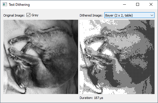
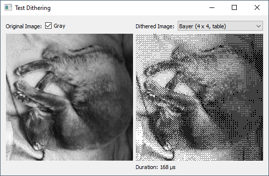
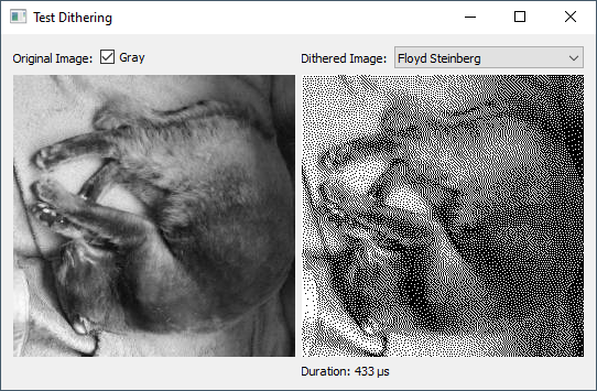
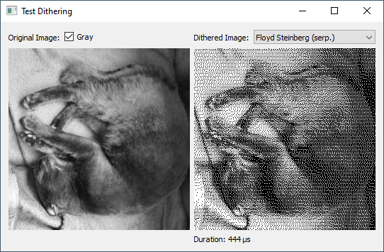
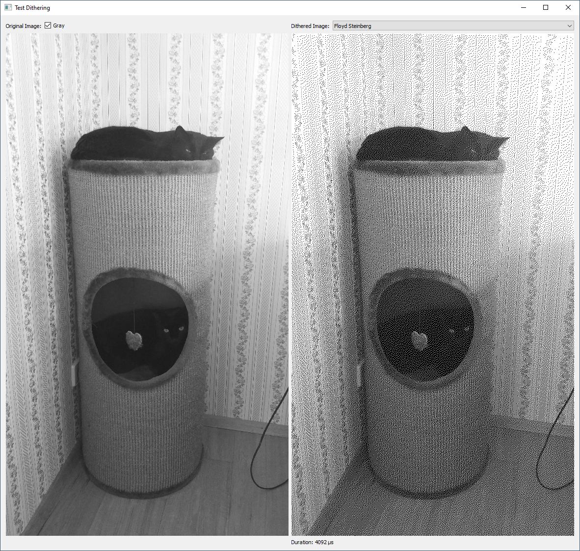
To compare the visual outcome of the different algorithms, I used a photo of one of my cats. I've chosen this as the cat is black. Hence, the photo consists of a lot of shades of gray which I consider as an ambitious task for a dithering algorithm.

Moritz, the cat
Moritz, the cat (256×256 pixel) – converted to graylevel for testing

Visual Output

Snapshot of testQImageDithering.exe - Bayer (2×2)
Bayer Dithering (2×2)

Snapshot of testQImageDithering.exe - Bayer (4×4)
Bayer Dithering (4×4)

Snapshot of testQImageDithering.exe - Bayer (8×8)
Bayer Dithering (8×8)

Snapshot of testQImageDithering.exe - Floyd-Steinberg
Floyd-Steinberg Dithering

Snapshot of testQImageDithering.exe - Floyd-Steinberg (serp.)
Floyd-Steinberg Dithering (in serpentines)

While this may give an impression of the visual outcome of the different dithering methods, the timings should be taken with a grain of salt.

Time Comparisons

While toying with the demo I noticed a high amount of noise in the output of computation durations. Hence, I use another image with 1024×576 pixels to get some timings. The following table provides a general impression without the claim to be considered as serious benchmark.

Method                  │ Duration (μs)
────────────────────────┼──────────────
Bayer (2 x 2, table)    │     1371
Bayer (4 x 4, table)    │     1368
Bayer (8 x 8, table)    │     1371
Bayer (2 x 2, func.)    │     1481
Bayer (4 x 4, func.)    │     1862
Bayer (8 x 8, func.)    │     2473
Floyd Steinberg         │     4037
Floyd Steinberg (serp.) │     4396

Findings:

  • For Bayer dithering with a pre-computed table, the size of the Bayer matrix has less impact.
  • This is not true when the Bayer matrix elements are computed on the fly (using a recursive function). That the recursion should be unrolled at compile-time doesn't change that fact.
  • The Floyd-Steinberg dithering is slower in general (although I consider the visual outcome as better).
  • The difference between Floyd-Steinberg and Floyd-Steinberg (serp.) is neglibible. (While toying, I saw the opposite relation as often as well.)

Snapshot of testQImageDithering.exe - with two cats to gain a better measurable performance impact


A sample image of OP:

Sample image of OP

Output:

Snapshot of testQImageDithering.exe - Bayer (2×2)

Snapshot of testQImageDithering.exe - Bayer (4×4)

Snapshot of testQImageDithering.exe - Bayer (8×8)

Snapshot of testQImageDithering.exe - Floyd-Steinberg

Snapshot of testQImageDithering.exe - Floyd-Steinberg (serp.)

Note:

After thinking twice about OPs 3d rendering… It's probably very easy to apply the Bayer dithering while it's not that easy for Floyd-Steinberg dithering (where each pixel influences the right and bottom neighbours).

Gaut answered 7/3, 2021 at 16:11 Comment(10)
nice +1 ... can you try some small image like this i.stack.imgur.com/Gyksu.png (I just added to question) so I can see how it behaves with low resolution and polygon like image which is my target right now. As many dithering methods require big enough target resolution to be usable ...Shuster
@Shuster Done. The background of the sample image is not that black as it looks like? Or do I still have a bug in my code?Lapidary
The one before last looks best I think, however hard to say if better or worse than mine output (and also in rotations and motion might look very different) maybe will try it if I have the time in few days...Shuster
Finally got some time for this ... I want to give it a try to use Floyd–Steinberg dithering however I can not use your code as I do not have grayscale image (nor its rowas/collumns ahead) I have just surface color of actual processed pixel which complicates things and rendering grayscale first is out of question due memory reasons ... the way convex polygons are rendering in last stage however might be used to apply this kind of dithering ... will see once I start code (have an idea how to overcome this problem) will let you know afterwards. Will see how it behaves on the edgesShuster
I did it ... however looks like my own render is nicer (for the flat shaded polygons). Have added edit to my answer with code and preview side by side comparison between mine and Floyd–Steinberg dithering. On the small LCD is not that bad and problems occur only in certain rotations ...Shuster
@Shuster I noticed the regular patterns in Floyd-Steinberg as well when I rendered your sample at Sunday evening. It was a bit surprising for me but I ignored it for then. I expected that Floyd-Steinberg is actually the algorithm to prevent this. However, this was short-handed. See this sample which results in a chess board. (It's actually a usual test, and the result is expect-able according to what I read on Wikipedia.) But I didn't think of that flat-shading results in exactly such images. Floyd-Steinberg surely has its strengths for photos... :-(Lapidary
@Shuster So, I think now what you did is actually a reasonable solution (and, strictly speaking, a variation of what the Bayer dithering does.)Lapidary
Yes by pure luck I evolved to correct solution at first hit... even the patterns I did contribute (Bayer would be worse) as the shades do not merge in artifacts on their joining sides ... (took me a while to figure how to paint it so it does what it does). The pattern size 8x8 was due to organization of VRAM of the LCD (its really weird)Shuster
@Shuster (Bayer would be worse) as the shades do not merge in artifacts on their joining sides Something else I noticed though I was not able to explain. I find your solution very deserves your check mark. :-) (I considered to try other dithering methods as well but I doubt that I will the find the time for this in the near future... ...and I've some doubts if it would improve anything concerning the quality and performance.)Lapidary
Yes I was waiting for the grace period (~2 days you can not check you own answer) to finish and also hoping for better answer but looks like there is not much to improve on this ... anyway thx for your feedback ... btw I also tried to set the pattern to move with face but that did not look as good as fixed position relative to screenShuster

© 2022 - 2024 — McMap. All rights reserved.