I've been working on audio project with STM32F4 discovery and I noticed one thing, all I2S standards only work with one microphone (depending which edge the standard uses separate bits). For exmpl. with Philips, MSB or LSB standards which are using falling edges as bit triggers, only catches the grounded L/R mic, and if I use PCM standard which uses rising edges as bit triggers, only catches the High L/R mic. I can't find a way to catch both MEMS mic samples in one period. Is the STM32F4 not capable of using to mics at once without external IC's?
The solution would be, to choose I2S data clock to be twice as fast as the clock of Mems microphone input, so that the processor, could catch the samples on either Mems clock pulse
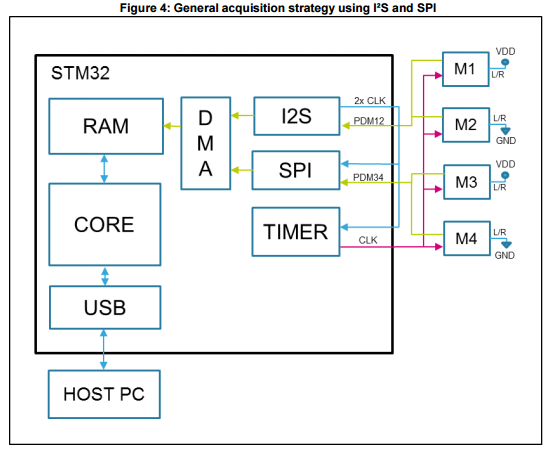
Just a follow up to the same question. One way of getting data from both of the microphones is making the microphone clock twice as smaller. You can do that by routing the I2S generated clock to a timer (which is set to output capture mode) at the ETR pin. Then using the timer you can divide it as you want. In this case twice. The timers output clock goes to both mics and their data is connected to the I2S data line (the same which is generating the clock). At the end you get I2S working twice as fast compared to the mics.
Here is an example with four microphone. (In your case just remove the SPI)
For more information read up on this.
You can try to use I2S2 and I2S3, the second to generate the clock for the mics and the first to generate the clock for sampling the pdm values (at a double rate), sharing the same PLL the clock should be synchronized. Doing so I think you can get the pdm bits by reading the recv register of the I2S2 but I also think that the bits from the 2 mics will be interleaved (a bit from mic 1, another from mic 2 and so on).
© 2022 - 2024 — McMap. All rights reserved.

