How to design a software workflow chart? [closed]
Asked Answered
G

3

11

I have been working for a while now but because of my earlier habits i never worked systematically.

I have never created a workflow chart for my software as how the software will work and instead of that i started working directly which in turn leads to many problems later.


Below is a small situation i currently need help with:-

NOTE:I have already created a software which does the following and i don't need any code for it, i just want to know how a workflow chart is created for such a situation.

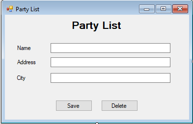
1) Party List : This is where i would like to store all of the information of my customer.

enter image description here

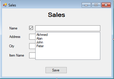
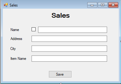
2) Sales : Here i will sell my products to the customer.

There are 2 cases here, whenever the customer arrives we have an option to

  • either save it in the party list and select it from the list in the sales form

enter image description here

  • or type it manually and then save it

enter image description here

Now comes the checking part:-

If an entry was saved in Sales when the checkbox was ticked and the user selected a party, lets say "Akhmed" has been saved AND the user tries to delete the record of "Akhmed" from the Party List form then the software shouldn't allow it to do so as the entry of "Akhmed" already exist in Sales.


Can anyone show me how a workflow chart is created for such a situation?

EDIT

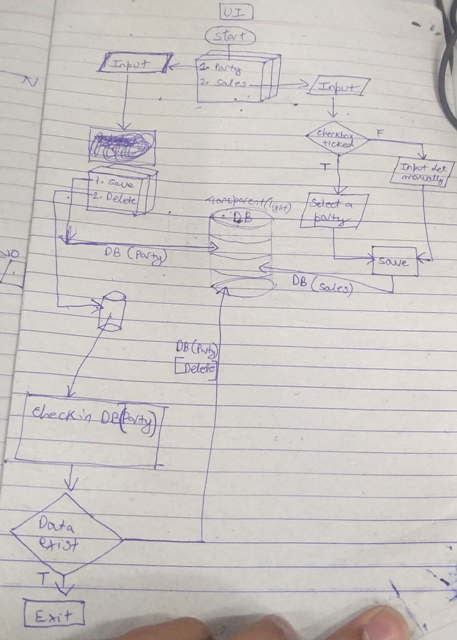
Here is a sample workflow i have made after reading some articles, please point out any improvements that can be made to it or is it completely wrong or anything.

enter image description here

Gastrolith answered 1/11, 2017 at 15:0 Comment(2)
Can you clarify what the purpose of the "workflow" is? Who is the intended audience? The answers will affect what level of detail is required and whether you are seeking a process flow, data flow, logic flow or otherwise. (See for instance conceptdraw.com/How-To-Guide/flowchart-types)Sergeant
@Sergeant sorry for the late reply, the thing i am looking for is that i want a flow chart diagram that contains every detail as to how the software should work so the software is bug proof. do you know how to make such a chart or any other information that might help me achieve such thingGastrolith
C
4

First of all, great question. I wish all software engineers thought first before jumping to writing a code. Especially when it's about anything more serious than a couple of lines for fun.

I think your software flow can be expressed as Activity diagram. An example of activity diagram is expressed on this picture: https://www.tutorialspoint.com/uml/images/uml_activity_diagram.jpg

Basically, activity diagram is a combination of steps and transitions (arrows) connecting them. Step can be just something that happens in the flow, or it can be a logical operator (decision) which branches the flow execution into different directions.

If you need to also emphasize who needs to execute the step, besides just showing what the steps are, you can add swimlanes (horizontal or vertical columns showing the actor names) to the activity diagram. That's where it turns into a Flow Chart diagram. e.g. on this image you can see horizontal swimplanes explaining who does the step execution http://static1.creately.com/blog/wp-content/uploads/2011/11/Support-Process-Flowchart-Template-1024x613.png

Note that terminology can differ from person to person, but these are the names for these 2 kinds of diagrams I have mostly heard and used myself.

There are other kinds of diagrams too, but I think your specific case will be covered with the ones mentioned above. Although... use case diagram can be something you may be interested in, but that does not depict steps. That only will mention actors and what kind of actions they can do with your system. e.g. https://sourcemaking.com/files/sm/images/uml/img_32.jpg

You didn't ask for tools, but I usually prefer to use tools that are rigor (rather than loose like Visio), so I would recommend to use WhiteStarUML. It's free and does a great job. But as I said, it's strictly UML-based, so will require some familiarity with UML.

Finally, about your attached picture: What you showed looks like an activity diagram with some illegal components on it (illegal from UML specification standpoint). Is it good or bad? - depends. If it's supposed to be a rigor UML diagram then it's bad. If it's just a sketch of an idea - not bad.

Your diagram mentions database sign (called "DB") and arrows connecting to it. That's illegal on an activity diagram UML. Instead, you can have a step which says "Data gets saved to Database", and remove the "DB". Also, you have a single step which says both "Party" and "Sales" on it - that's not a legal UML. I think you tried to express that there are 2 flows. In that case, just have 2 different activity diagrams instead of one.

Country answered 10/11, 2017 at 23:10 Comment(2)
Thanks for the answer mate, i want to ask that what kind of illegal components are mentioned in my sketch (my diagram) and i was planning to make a new tool for myself as i cant find a decent and elegant diagram tool for it.Gastrolith
I just added an additional paragraph with the information about what's exactly illegal in your activity/flowchart diagram. As about tool - I mentioned WhiteStarUML - that's a very powerful UML tool. It can create all kinds of UML diagrams based on UML specification. It can also export diagrams as pictures if needed. Try that and if you can create a better one, keep me informed.Country
S
3

Your question is quite broad but I'll give it a shot.

I think you want to reconsider your approach. I would suggest reading up on UML sequence diagrams. They are a kind of diagram that provides a way to represent how requests are made within code. UML, in general, can also be used to make class diagrams and other useful flow-like charts for representing code. Many tools, such as visual-paradigm, allow you to build UML diagrams (ex. class diagrams)that can be converted directly into code. This can be useful when getting you started on the program. There is a learning curve with using these tools as different kinds of arrows mean different things, but they can be very powerful. they can also be used to take existing code and convert it to a diagram, which is great when trying to explain how your program works.

here are some other links that might be useful:

lucidchart has an example of a pop-up window diagram like the one you described.

draw.io just allows for you to make the diagrams, not convert them to code, but it is an easy to use tool and integrates with google drive and git hub.

stackoverflow has some info on UML too.

If you are looking for a "professional workflow diagram" UML if a fine way to go, there are many ways they can be laid out and they can be quite professional, I learned about them in school and have used them at work to help plan out the flow of data through our system. There are many more UML tools out there, it might be worth looking into a tutorial to find what's best for you.

Shulem answered 7/11, 2017 at 18:46 Comment(0)
G
1

You seem to be on the right track, I have never added a database to my flow-charts but it is up to you on how detailed you want to get. You seem to be using the correct symbols!

Here is an awesome, free website that I use. https://www.draw.io/ it was created for making flow charts and other things.

I personally would remove the UI at the beginning of your chart. Try to stay away from the overly technical examples when starting out with flow-charts, hit up YouTube or Google images for some simple, but correct examples.

Good luck friend!

Gammy answered 11/11, 2017 at 21:42 Comment(0)

© 2022 - 2024 — McMap. All rights reserved.