An algorithm for inflating/deflating (offsetting, buffering) polygons
Asked Answered
B

15

243

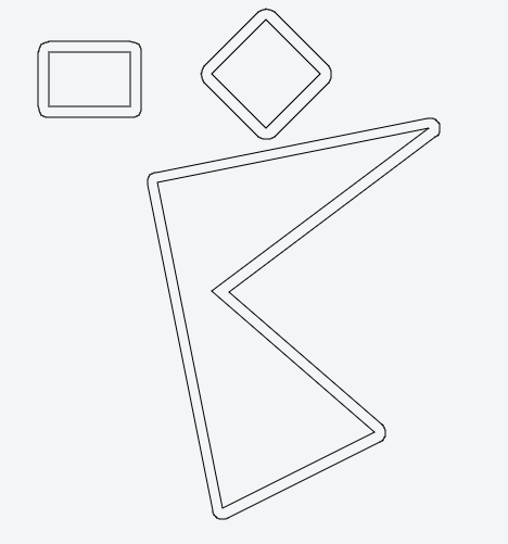
How would I "inflate" a polygon? That is, I want to do something similar to this:

alt text

The requirement is that the new (inflated) polygon's edges/points are all at the same constant distance from the old (original) polygon's (on the example picture they are not, since then it would have to use arcs for inflated vertices, but let's forget about that for now ;) ).

The mathematical term for what I'm looking for is actually inward/outward polygon offseting. +1 to balint for pointing this out. The alternative naming is polygon buffering.

Results of my search:

Here are some links:

Bimestrial answered 10/7, 2009 at 13:32 Comment(6)
This is not at all a trivial question: if the deflation / inflation is small, nothing serious happens, but at some point, vertices will disappear. Probably this has been done before, so I'd say: use someone else's algorithm, don't build your own.Hilten
Indeed, if your polygon is concave to start with (as in the example above) you have to decide what should happen at the point where the naive algorithm wants to make a self-intersecting 'polygon'...Halm
Yes, the main problem are the concave parts of the polygon, this is where the complexity lies. I still think it shouldn't be such a problem to calculate when a certain vertex has to be eliminated. The main question is what kind of asymptotic complexity this would require.Bimestrial
Hello, this is also my problem, except I need to do this in 3D. Is there an alternative to the Straight Skeletons of Three-Dimensional Polyhedra approach described in the paper arxiv.org/pdf/0805.0022.pdf?Schnitzler
Another name for these are parallel curves, to offset the contour/outline: en.wikipedia.org/wiki/Parallel_curveManxman
checkout this answer for JavaScript refrence.Henpeck
M
168

August 2022:
Clipper2 has now been formally released and it supersedes Clipper (aka Clipper1).


I thought I might briefly mention my own polygon clipping and offsetting library - Clipper.

While Clipper is primarily designed for polygon clipping operations, it does polygon offsetting too. The library is open source freeware written in Delphi, C++ and C#. It has a very unencumbered Boost license allowing it to be used in both freeware and commercial applications without charge.

Polygon offsetting can be performed using one of four styles (or Join Types) - mitered, squared, bevel and round.
mitered square bevel round
Note: In JoinType.Miter, the inner angle at vertex A is more acute than the one at B and the mitered offset at A would exceed the specified miter limit of 2.

Masurium answered 30/10, 2011 at 19:52 Comment(19)
Very cool! Where were you 2 years ago? :) In the end I had to implement my own offsetting logic (and lost a lot of time at it). What algorithm are you using for polygon offsetting, BTW? I used grassfire. Do you handle holes in polygons?Bimestrial
2 years ago I was looking for a decent solution to polygon clipping that wasn't encumbered with tricky licence issues :). Edge offsetting is achieved by generating unit normals for all the edges. Edge joins are tidied by my polygon clipper since the orientations of these overlapped intersections are opposite the orientation of the polygons. Holes are most certainly handled as are self-intersecting polygons etc. There are no restrictions to their type or number. See also "Polygon Offsetting by Computing Winding Numbers" here: me.berkeley.edu/~mcmains/pubs/DAC05OffsetPolygon.pdfMasurium
Whoa! Don't for a second think this question is "forgotten"! I looked here last week -- I wasn't expecting to come back to this! Thanks a bunch!Obvert
Clipper's docs on poly buffering are here: angusj.com/delphi/clipper/documentation/Docs/Units/ClipperLib/…Hokusai
For anyone that wants to do this, another alternative is to use GEOS, and if your using python, GEOS's wrapper, Shapely. A really pretty example: toblerity.github.com/shapely/manual.html#object.bufferCatamite
Clipper is now available also for Javascript in SourceForge. See the demo: jsclipper.sourceforge.net/5.0.2.1/main_demo.html and manual for demo: sourceforge.net/p/jsclipper/wiki/Main_Demo .Whip
...so as it turns out, after struggling with this issue for about a year, I finally got around to Google searching and found this answer. I was already using the Clipper library, but had no idea this functionality was built into it!Beaufort
@TrevorPowell Programming has come to the point where searching for code is more useful than writing code more often than not.Natterjack
@AngusJohnson Does this work with 3d objects as well?Natterjack
@Arthur Wulf White: No.Masurium
@Timo the link requires a login. links should directly open.Orientation
@Catamite the link is dead.Orientation
Sorry, I changed the page. This is a working link to the Clipper 5 demo page: sourceforge.net/p/jsclipper/wiki/Main_Demo%205. However better to browse the newest versions: jsclipper.sourceforge.net/6.1.3.2/main_demo.html sourceforge.net/p/jsclipper/wiki/Main_Demo%206.Whip
Does Clipper handle large, irregularly shaped polygons like the ones in balint.miklos's answer? Some big name libraries, like Boost Geometry, don't handle them well.Venator
Is this also available for 3D data, e.g. polyeders?Schnitzler
Clipper is very neat, but its offsetting often does the wrong thing, for my needs at least. I need the result to have a line parallel to every edge in the original polygon, unless that entire edge would disappear after the offset, but Clipper often takes it upon itself to cull away entire edges (or a whole series of edges!). A complex polygon, inset a bit, may result in nothing but a triangle over on one edge, the rest completely gone. Just thought folks should be forewarned.Stomacher
I need to apply an offset that is different for each edge. Can it handle it?Gree
does the api only allow to create polyline from integer point (IntPoint) ? can I not have double precision point?Elah
python wrapper: github.com/fonttools/pyclipperVinny
W
48

The polygon you are looking for is called inward/outward offset polygon in computational geometry and it is closely related to the straight skeleton.

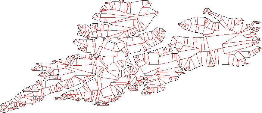
These are several offset polygons for a complicated polygon:

And this is the straight skeleton for another polygon:

As pointed out in other comments, as well, depending on how far you plan to "inflate/deflate" your polygon you can end up with different connectivity for the output.

From computation point of view: once you have the straight skeleton one should be able to construct the offset polygons relatively easily. The open source and (free for non-commercial) CGAL library has a package implementing these structures. See this code example to compute offset polygons using CGAL.

The package manual should give you a good starting point on how to construct these structures even if you are not going to use CGAL, and contains references to the papers with the mathematical definitions and properties:

CGAL manual: 2D Straight Skeleton and Polygon Offsetting

Williwaw answered 10/7, 2009 at 16:25 Comment(0)
F
18

For these types of things I usually use JTS. For demonstration purposes I created this jsFiddle that uses JSTS (JavaScript port of JTS). You just need to convert the coordinates you have to JSTS coordinates:

function vectorCoordinates2JTS (polygon) {
  var coordinates = [];
  for (var i = 0; i < polygon.length; i++) {
    coordinates.push(new jsts.geom.Coordinate(polygon[i].x, polygon[i].y));
  }
  return coordinates;
}

The result is something like this:

enter image description here

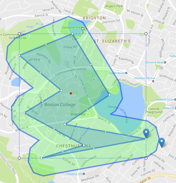
Additional info: I usually use this type of inflating/deflating (a little modified for my purposes) for setting boundaries with radius on polygons that are drawn on a map (with Leaflet or Google maps). You just convert (lat,lng) pairs to JSTS coordinates and everything else is the same. Example:

enter image description here

Fellatio answered 26/8, 2016 at 9:55 Comment(0)
O
12

Sounds to me like what you want is:

  • Starting at a vertex, face anti-clockwise along an adjacent edge.
  • Replace the edge with a new, parallel edge placed at distance d to the "left" of the old one.
  • Repeat for all edges.
  • Find the intersections of the new edges to get the new vertices.
  • Detect if you've become a crossed polygon and decide what to do about it. Probably add a new vertex at the crossing-point and get rid of some old ones. I'm not sure whether there's a better way to detect this than just to compare every pair of non-adjacent edges to see if their intersection lies between both pairs of vertices.

The resulting polygon lies at the required distance from the old polygon "far enough" from the vertices. Near a vertex, the set of points at distance d from the old polygon is, as you say, not a polygon, so the requirement as stated cannot be fulfilled.

I don't know if this algorithm has a name, example code on the web, or a fiendish optimisation, but I think it describes what you want.

Olid answered 10/7, 2009 at 13:41 Comment(0)
M
7

In the GIS world one uses negative buffering for this task: http://www-users.cs.umn.edu/~npramod/enc_pdf.pdf

The JTS library should do this for you. See the documentation for the buffer operation: http://tsusiatsoftware.net/jts/javadoc/com/vividsolutions/jts/operation/buffer/package-summary.html

For a rough overview see also the Developer Guide: http://www.vividsolutions.com/jts/bin/JTS%20Developer%20Guide.pdf

Musicianship answered 9/11, 2010 at 8:43 Comment(0)
I
5

Each line should split the plane to "inside" and "outline"; you can find this out using the usual inner-product method.

Move all lines outward by some distance.

Consider all pair of neighbor lines (lines, not line segment), find the intersection. These are the new vertex.

Cleanup the new vertex by removing any intersecting parts. -- we have a few case here

(a) Case 1:

 0--7  4--3
 |  |  |  |
 |  6--5  |
 |        |
 1--------2

if you expend it by one, you got this:

0----a----3
|    |    |
|    |    |
|    b    |
|         |
|         |
1---------2

7 and 4 overlap.. if you see this, you remove this point and all points in between.

(b) case 2

 0--7  4--3
 |  |  |  |
 |  6--5  |
 |        |
 1--------2

if you expend it by two, you got this:

0----47----3
|    ||    |
|    ||    |
|    ||    |
|    56    |
|          |
|          |
|          |
1----------2

to resolve this, for each segment of line, you have to check if it overlap with latter segments.

(c) case 3

       4--3
 0--X9 |  |
 |  78 |  |
 |  6--5  |
 |        |
 1--------2

expend by 1. this is a more general case for case 1.

(d) case 4

same as case3, but expend by two.

Actually, if you can handle case 4. All other cases are just special case of it with some line or vertex overlapping.

To do case 4, you keep a stack of vertex.. you push when you find lines overlapping with latter line, pop it when you get the latter line. -- just like what you do in convex-hull.

Ingham answered 10/7, 2009 at 13:40 Comment(1)
do you know any psedo algorithm for this.Ptisan
I
5

Here is an alternative solution, see if you like this better.

  1. Do a triangulation, it don't have to be delaunay -- any triangulation would do.

  2. Inflate each triangle -- this should be trivial. if you store the triangle in the anti-clockwise order, just move the lines to right-hand-side and do intersection.

  3. Merge them using a modified Weiler-Atherton clipping algorithm

Ingham answered 10/7, 2009 at 13:54 Comment(6)
how do you inflate the triangles exactly? Does your output depend on the triangulation? With this approach can you handle the case when you shrink the polygon?Williwaw
Are you sure this approach really works for polygon inflation? What happens when the concave parts of the polygon are inflated to such extent that some vertices have to be eliminated. The thing is: when you look what happens to triangles after poly. inflation, the triangles are not inflated, instead they are distorted.Bimestrial
Igor: Weiler-Atherton clipping algorithm can handle the "some vertices have to be eliminated" case correctly;Ingham
@balint: inflate an triangle is trivial: if you store the vertrex in normal order, the right-hand-side is always "outward". Just treat those line segment as lines, move them outward, and find the interaction -- they are the new vertex. For the triangulation itself, on a second thought, delaunay triangulation may give better result.Ingham
Note: If you implement everything from the ground up, this method is more complex then the another method i have proposal. However, if you have a good computational geometry library, both (1) and (3) are standard algorithm and should be readily available.Ingham
I think this approach can easily give bad results. Even for a simple example as quad triangulated using a diagonal. For the two enlarged triangles you get: img200.imageshack.us/img200/2640/counterm.png and their union is just not what you are looking for. I don't see how this method is useful.Williwaw
O
5

Big thanks to Angus Johnson for his clipper library. There are good code samples for doing the clipping stuff at the clipper homepage at http://www.angusj.com/delphi/clipper.php#code but I did not see an example for polygon offsetting. So I thought that maybe it is of use for someone if I post my code:

    public static List<Point> GetOffsetPolygon(List<Point> originalPath, double offset)
    {
        List<Point> resultOffsetPath = new List<Point>();

        List<ClipperLib.IntPoint> polygon = new List<ClipperLib.IntPoint>();
        foreach (var point in originalPath)
        {
            polygon.Add(new ClipperLib.IntPoint(point.X, point.Y));
        }

        ClipperLib.ClipperOffset co = new ClipperLib.ClipperOffset();
        co.AddPath(polygon, ClipperLib.JoinType.jtRound, ClipperLib.EndType.etClosedPolygon);

        List<List<ClipperLib.IntPoint>> solution = new List<List<ClipperLib.IntPoint>>();
        co.Execute(ref solution, offset);

        foreach (var offsetPath in solution)
        {
            foreach (var offsetPathPoint in offsetPath)
            {
                resultOffsetPath.Add(new Point(Convert.ToInt32(offsetPathPoint.X), Convert.ToInt32(offsetPathPoint.Y)));
            }
        }

        return resultOffsetPath;
    }
Outhouse answered 24/11, 2016 at 8:14 Comment(0)
L
2

One further option is to use boost::polygon - the documentation is somewhat lacking, but you should find that the methods resize and bloat, and also the overloaded += operator, which actually implement buffering. So for example increasing the size of a polygon (or a set of polygons) by some value can be as simple as:

poly += 2; // buffer polygon by 2
Ludivinaludlew answered 24/2, 2016 at 8:43 Comment(10)
I don't understand how you are supposed to do anything with boost::polygon since it only supports integer coordinates? Say I have a general (floating point coordinates) polygon and I want to expand it - what would I do?Brit
@DavidDoria: it depends on what resolution/accuracy and dynamic range you need for your coordinates, but you could use a 32 bit or 64 bit int with an appropriate scaling factor. Incidentally I have (accidentally) used boost::polygon with float coordinates in the past and it seems to work OK, but it may not be 100% robust (the docs warn against it!).Ludivinaludlew
I'd be ok with "it'll work work most of the time" :). I tried this: ideone.com/XbZeBf but it doesn't compile - any thoughts?Brit
I don't see anything obviously wrong, but in my my case I was using the rectilinear specialisations (polygon_90) so I don't know if that makes a difference. It's been a few years since I played around with this though.Ludivinaludlew
OK - it's coming back to me now - you can only use += with a polygon set, not with individual polygons. Try it with a std::vector of polygons. (Of course the vector need only contain one polygon).Ludivinaludlew
That compiles, but unfortunately it seems that they weren't kidding that it only works with integer types: ideone.com/laiKcT You can see that bufffering with radius '1' works as expected (the unit cube becomes area 9), but buffering with radius '0.1' does NOT work as expected (the expanded unit cube still has area 1).Brit
OK - maybe best to take heed of the docs then and maybe consider using a fixed point approach (i.e. integer coords and implicit scaling factor) ?Ludivinaludlew
So you're saying if I have points like 1.2345, I should just multiply everything by 10000 to get a value like 12345, then do the operations, then divide by 10000 to get back to my original coordinate system? With the idea being that I will loose precision past the 4th decimal (and whatever function of that happens depending on the operation/function that is used).Brit
Yes, although it's more common to use a power of 2 scale factor to get fixed point, as it makes the scaling a lot more efficient, e.g. treat your 32 bit int coords as 16.16 fixed point (16 bit integer, 16 bit fraction). Choice of # of bits for int part and fraction depends on your required accuracy/resolution and range.Ludivinaludlew
CGAL has this feature for 2D. By any changes somebody knows if there is some code for 3D?Schnitzler
S
1

Based on advice from @JoshO'Brian, it appears the rGeos package in the R language implements this algorithm. See rGeos::gBuffer .

Sonata answered 7/8, 2013 at 20:11 Comment(0)
H
1

I use simple geometry: Vectors and/or Trigonometry

  1. At each corner find the mid vector, and mid angle. Mid vector is the arithmetic average of the two unit vectors defined by the edges of the corner. Mid Angle is the half of the angle defined by the edges.

  2. If you need to expand (or contract) your polygon by the amount of d from each edge; you should go out (in) by the amount d/sin(midAngle) to get the new corner point.

  3. Repeat this for all the corners

*** Be careful about your direction. Make CounterClockWise Test using the three points defining the corner; to find out which way is out, or in.

Healey answered 24/3, 2019 at 12:34 Comment(0)
P
1

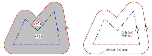
To inflate a polygon, one can implement the algorithm from "Polygon Offsetting by Computing Winding Numbers" article.

The steps of the algorithm are as follows:

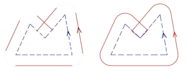
  1. Construct outer offset curve by taking every edge from input polygon and shifting it outside, then connecting shifted edged with circular arches in convex vertices of input polygon and two line segments in concave vertices of input polygon.

An example. Here input polygon is dashed blue, and red on the left - shifted edges, on the right - after connecting them in continuous self-intersecting curve:

Offset edges

  1. The curve divides the plane on a number of connected components, and one has to compute the winding number in each of them, then take the boundary of all connected components with positive winding numbers:

Winding numbers

The article proofs that the algorithm is very fast compared to competitors and robust at the same time.

To avoid implementing winding number computation, one can pass self-intersecting offset curve to OpenGL Utility library (GLU) tessellator and activate the settings GLU_TESS_BOUNDARY_ONLY=GL_TRUE (to skip triangulation) and GLU_TESS_WINDING_RULE=GLU_TESS_WINDING_POSITIVE (to output the boundary of positive winding number components).

Phaedra answered 17/2, 2023 at 18:42 Comment(0)
S
0

There are a couple of libraries one can use (Also usable for 3D data sets).

  1. https://github.com/otherlab/openmesh
  2. https://github.com/alecjacobson/nested_cages
  3. http://homepage.tudelft.nl/h05k3/Projects/MeshThickeningProj.htm

One can also find corresponding publications for these libraries to understand the algorithms in more detail.

The last one has the least dependencies and is self-contained and can read in .obj files.

Schnitzler answered 6/7, 2018 at 16:52 Comment(4)
Does this work for Internally offsetting the Polygon ? (a negative distance ??)Crotch
@RudyVanDrie I would say, yes, but just give it a try.Schnitzler
The last link does not work on 10/12/22Bobble
Did not find another link, maybe you?Schnitzler
B
0

This is a C# implementation of the algorithm explained in here . It is using Unity math library and collection package as well.

public static NativeArray<float2> ExpandPoly(NativeArray<float2> oldPoints, float offset, int outer_ccw = 1)
{
    int num_points = oldPoints.Length;
    NativeArray<float2> newPoints = new NativeArray<float2>(num_points, Allocator.Temp);

    for (int curr = 0; curr < num_points; curr++)
    {
        int prev = (curr + num_points - 1) % num_points;
        int next = (curr + 1) % num_points;

        float2 vn = oldPoints[next] - oldPoints[curr];
        float2 vnn = math.normalize(vn);
        float nnnX = vnn.y;
        float nnnY = -vnn.x;

        float2 vp = oldPoints[curr] - oldPoints[prev];
        float2 vpn = math.normalize(vp);
        float npnX = vpn.y * outer_ccw;
        float npnY = -vpn.x * outer_ccw;

        float bisX = (nnnX + npnX) * outer_ccw;
        float bisY = (nnnY + npnY) * outer_ccw;

        float2 bisn = math.normalize(new float2(bisX, bisY));
        float bislen = offset / math.sqrt((1 + nnnX * npnX + nnnY * npnY) / 2);

        newPoints[curr] = new float2(oldPoints[curr].x + bislen * bisn.x, oldPoints[curr].y + bislen * bisn.y);
    }

    return newPoints;
}
Bushbuck answered 21/7, 2022 at 6:20 Comment(1)
Just a quick note. I spoke with the original algorithm author. He had a mistake in bislen. The correct formula should be. float bislen = offset / math.sqrt((1 + nnnX * npnX + nnnY * npnY)/2); There was a divide by 2 missing. The original answer has been updated.Cabby
C
0

Thanks for the help in this topic, here's the code in C++ if anyone interested. Tested it, its working. If you give offset = -1.5, it will shrink the polygon.

    typedef struct {
        double x;
        double y;
    } Point2D;
    
    double Hypot(double x, double y)
    {
        return std::sqrt(x * x + y * y);
    }
    
    Point2D NormalizeVector(const Point2D& p)
    {
        double h = Hypot(p.x, p.y);
        if (h < 0.0001)
            return Point2D({ 0.0, 0.0 });
    
        double inverseHypot = 1 / h;
        return Point2D({ (double)p.x * inverseHypot, (double)p.y * inverseHypot });
    }
    
    void offsetPolygon(std::vector<Point2D>& polyCoords, std::vector<Point2D>& newPolyCoords, double offset, int outer_ccw)
    {
        if (offset == 0.0 || polyCoords.size() < 3)
            return;
    
        Point2D vnn, vpn, bisn;
        double vnX, vnY, vpX, vpY;
        double nnnX, nnnY;
        double npnX, npnY;
        double bisX, bisY, bisLen;
    
        unsigned int nVerts = polyCoords.size() - 1;
    
        for (unsigned int curr = 0; curr < polyCoords.size(); curr++)
        {
            int prev = (curr + nVerts - 1) % nVerts;
            int next = (curr + 1) % nVerts;
    
            vnX = polyCoords[next].x - polyCoords[curr].x;
            vnY = polyCoords[next].y - polyCoords[curr].y;
            vnn = NormalizeVector({ vnX, vnY });
            nnnX = vnn.y;
            nnnY = -vnn.x;
    
            vpX = polyCoords[curr].x - polyCoords[prev].x;
            vpY = polyCoords[curr].y - polyCoords[prev].y;
            vpn = NormalizeVector({ vpX, vpY });
            npnX = vpn.y * outer_ccw;
            npnY = -vpn.x * outer_ccw;
    
            bisX = (nnnX + npnX) * outer_ccw;
            bisY = (nnnY + npnY) * outer_ccw;
    
            bisn = NormalizeVector({ bisX, bisY });
            bisLen = offset / std::sqrt((1 + nnnX * npnX + nnnY * npnY) / 2);
    
            newPolyCoords.push_back({ polyCoords[curr].x + bisLen * bisn.x, polyCoords[curr].y + bisLen * bisn.y });
        }
    }
Cutout answered 27/1, 2023 at 11:13 Comment(0)

© 2022 - 2024 — McMap. All rights reserved.