How to draw a Control Flow Graph from this code?
Asked Answered
S

3

9
int main() {
    int i, grade = 0;
    printf (" Enter points: \n");
    scanf ("%d", &i);
    if (i >= 50 && i <= 60) grade = 5;
    else if (i > 50 && i <= 60) grade = 6;
    else if (i > 60 && i <= 70) grade = 7;
    else if (i > 70 && i <= 80) grade = 8;
    else if (i > 80 && i <= 90) grade = 9;
    else if (i > 90 && i <= 100) grade = 10;
    char sign = ' ';
    if (grade) {
        int p = i % 10;
        if (grade != 5) {
            if (p >= 1 && p <= 3)
                sign = '-';
            else if (grade != 10 && (p >= 8 || p == 0))
                sign = '+';
        }
        printf (" The grade is %d%c. \n", grade, sign);

    }
    return 0;
}

How do I draw Control Flow Graph from this code? I'll appreciate if someone can show the process. I am able to draw CFG from a very simple cases but I cannot do this one. Also I need to determine the basis paths and the tests for Multiple Condition criteria. It's not a homework question, I just try to understand the course material. Thanks.

Stark answered 18/6, 2018 at 16:20 Comment(2)
Are you sure this is Java and not C?Tyishatyke
Oh, I'm sorry I've added Java, it is not, it's C but that is irrelevant.Stark
K
29

Here's the definition of CFG from Wikipedia, I know you already know this but for the sake of completeness I'm putting it here

A control flow graph (CFG) in computer science is a representation, using graph notation, of all paths that might be traversed through a program during its execution.

Ref: https://en.wikipedia.org/wiki/Control_flow_graph

Following is the definition of a Path

Path: a sequence of node on the CFG (static), including an entry node and an exit node; path segment: a subsequence of nodes along the path

Ref: http://web.cs.iastate.edu/~weile/cs513x/4.ControlFlowAnalysis.pdf

So the reason for drawing one would be to determine all possible paths taken by the program, which may help us determine things like test coverage without actually running the program (static analysis).

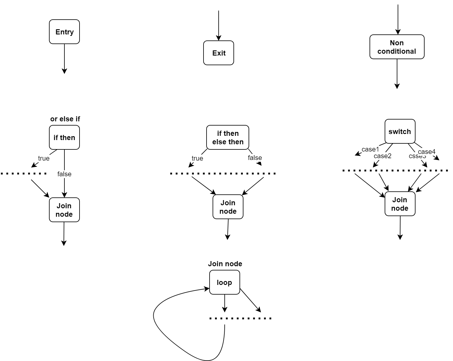
Following are the simple rules that we can follow to draw a CFG

  1. Any statement will be a node in graph
  2. All nodes have a directed edge either coming to them or going out of them or both. Entry node (first statement) has only outgoing edges and Exit node has only incoming edges.
  3. only conditional statements like if/else if, switch, loops would have more than one outgoing edges.
  4. All paths coming out of a node will converge at some point, in worst case they converge on Exit.

Here's a cheat sheet which explains it better

CFG cheat sheet

Now lets map every statement in your program to an number that we'll use to denote CFG nodes

   int main() {
1.     int i, grade = 0;
2.     printf (" Enter points: \n");
3.     scanf ("%d", &i);
4.     if (i >= 50 && i <= 60)
5.         grade = 5;
6.     else if (i > 50 && i <= 60)
7.         grade = 6;
8.     else if (i > 60 && i <= 70)
9.         grade = 7;
10.    else if (i > 70 && i <= 80)
11.         grade = 8;
12.    else if (i > 80 && i <= 90)
13.         grade = 9;
14.    else if (i > 90 && i <= 100)
15.         grade = 10;
16.    char sign = ' ';
17.    if (grade) {
18.        int p = i % 10;
19.        if (grade != 5) {
20.            if (p >= 1 && p <= 3)
21.                sign = '-';
22.            else if (grade != 10 && (p >= 8 || p == 0))
23.                sign = '+';
           }
24.        printf (" The grade is %d%c. \n", grade, sign);
       }
25.    return 0;
  }

Here's the output created by following the directions from cheat sheet diagram above. Notice that node 16 and 24 are acting as join node for many conditional nodes before.

enter image description here

Credit: I have used draw.io to create images posted above.

Note: Secret to drawing a CFG is to treat every statement independent to the program, draw it and then link it's entry and exit to the rest of the graph.

Following are a few initial steps that I followed

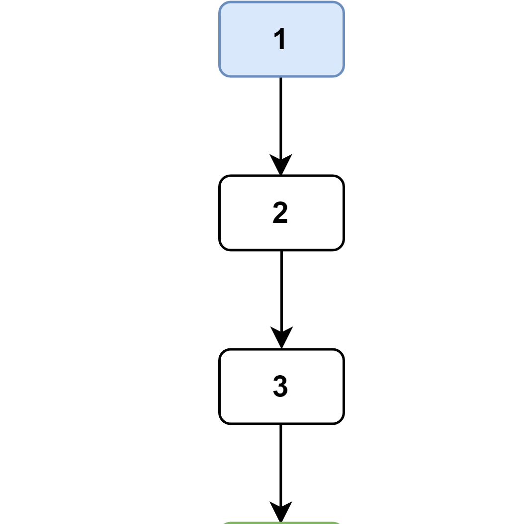
  1. Statement 1, 2, and 3 are non conditional so I created three blocks linking them together. step1
  2. Statement 4 is a conditional statement. So I have to create 4 blocks for it. First for for statement 4, second and third for TRUE, FALSE edges, and lastly one for JOIN node. If true then statement 5 is run if not then we go to statement 6. From statement 5 we directly go to statement 16, which is our join node. Finally we link block 4 to bock 3's out going edge. enter image description here
  3. Now statement 6 itself is a conditional statement so we again need 4 blocks for it. We already have one for itself block 6. Join node for it will be statement 16 as if it's condition is true then statement 7 is run and it directly goes to 16. Now we already have block 6 and 16 so we just need blocks for TRUE, FALSE branches which are statement 7 and 8. step3

And so on, we keep checking the cheat sheet for the applicable nodes and create them in isolation then link then with previous nodes.

Khoisan answered 30/6, 2018 at 9:8 Comment(7)
Great explanation. After studying it thoroughly, there is one thing missing in this diagram. There has to be a node for every statement in the conditionals, they shouldn't be considered as one statement leading true or false. For example, if the first statement in the conditional is true, the program goes to another node and that's the second statement in the conditional(then third, fourth etc.). This results to greater complexity too.Stark
I'm not sure that I understand, for a conditional node like if/else if there can be only two and only two edges going out of it. Can you please post an example or a link of the graph that you've mentioned? Control flow graph would mostly resemble the flow chart diagram.Khoisan
imgur.com/zEXaSsY. Here I've drawn a diagram for a case. The complexity is 4 in this diagram, and if you draw it like you said, it'll be two.Stark
Oh, you mean every boolean expression in condition would be counted as one separate statement, yes I can see how that would give interesting information about the flow regarding short circuiting.Khoisan
And actually the complexity will be 5 because you need to add one more edge from x = 100 to an edge that follows y = 100.Stark
May I borrow the first picture?Yancy
Yes, you can use all the imagesKhoisan
F
6

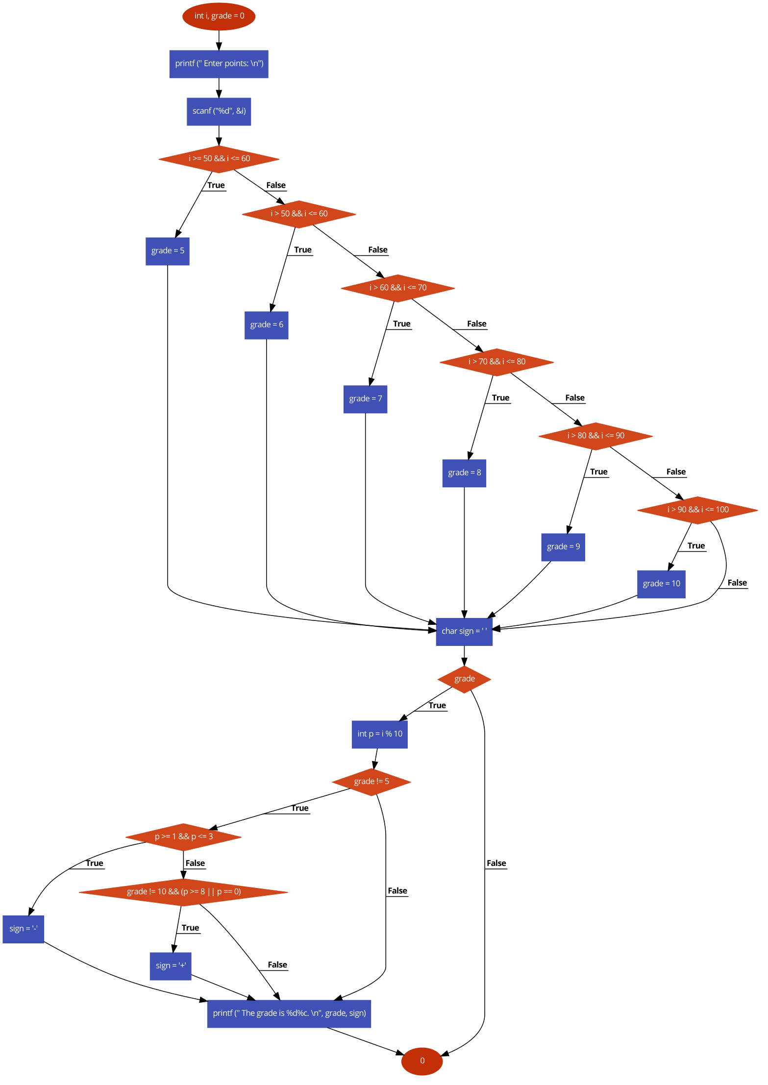
If we should explain a flow diagram so why we draw it? the diagram must be so clear.

control flow diagram

there are lots of online tools that you can type your code and that will give you this like diagram. you can check this.

Factious answered 25/6, 2018 at 8:25 Comment(3)
This is not a CFG, but control flow diagram. They are different.Stark
CFG only has basic blocks, however, this graph contains statements.Emir
Seems like an advertisement for your service -1Bolger
Q
1

My c front-end tool Crokus (available on both github and rubygems) gives that directly from parsing your C code.

enter image description here

Quartan answered 5/6, 2020 at 10:55 Comment(1)
note that grade has not been initialized correctly. I will fix that one day.Quartan

© 2022 - 2024 — McMap. All rights reserved.